Installing Peripherals (Parallel/Serial/ Ethernet) 5-4
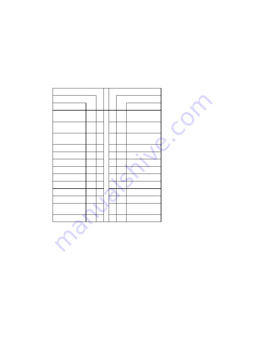
The following table shows the pinout for this connecter, when it is in ECP mode:
TABLE 5-3:
Printer Parallel Port (J13) - ECP Mode
Pin Number
Pin Number
Signal Flow
Signal Flow
Signal
Signal
STROBE*
O
1
2
O
AUTOFD*,
HOSTACK
3
D0
I/O
3
4
I
FAULT*
1
,
PERIPHRQST*
3
D1
I/O
5
6
O
INIT*
1
,
REVERSERQST*
3
D2
I/O
7
8
O
SELECTIN*
1,3
D3
I/O
9
10
-
GND
D4
I/O
11
12
-
GND
D5
I/O
13
14
-
GND
D6
I/O
15
16
-
GND
D7
I/O
17
18
-
GND
ACK*
I
19
20
-
GND
BUSY, PERIPHACK
3
I
21
22
-
GND
PERROR,
ACKREVERSE
3
I
23
24
-
GND
SELECT
I
25
26
-
GND
* Active low signal
1
Compatible Mode
2
High Speed Mode
Note: For more information on the ECP protocol, please refer to the Extended Capabilities
Port Protocol and ISA Interface Standard (available from Microsoft Corporation) or
contact our Technical Support department.
Summary of Contents for VIPer808
Page 21: ...Installing Memory 2 3 DIAGRAM 2 1 Assembly Top...
Page 22: ...Installing Memory 2 5 DIAGRAM 2 2 Assembly Bottom...
Page 26: ...Setting Jumpers 3 3 DIAGRAM 3 1 VIPer808 Jumper Locations with Default Settings...
Page 28: ...Setting Jumpers 3 6 TABLE 3 1a Jumper Settings W1 W4 W13 W14...
Page 29: ...Setting Jumpers 3 7 TABLE 3 1b AMD DX2 DX4 CPU Jumper Settings W1 W15 W15C...
Page 30: ...Setting Jumpers 3 8 TABLE 3 1c AMD 5x86 CPU Jumper Settings W1 W15 W15C...
Page 31: ...Setting Jumpers 3 9 TABLE 3 1d Intel CPU Jumper Settings W1 W15 W15C...
Page 32: ...Setting Jumpers 3 10 TABLE 3 1e SGS CPU Jumper Settings W1 W15 W15C...
Page 33: ...Setting Jumpers 3 11 TABLE 3 1f Jumper Settings W18 W20 W23...
Page 92: ...Memory I O Maps B 1 APPENDIX B MEMORY I O MAPS B 01 MEMORY MAPS DIAGRAM B 1 Memory Map Diagram...
Page 96: ...Mechanical Layout Block Diagram C 3 DIAGRAM C 1 Mechanical Specifications...


