TEK-NTS03-G+-Manual-v3.-012022
P a g e
| 13
www.tekron.com
© 2022 by Tekron International Limited. All Rights Reserved. All trademarks are the property of their respective holders. The
information in this document is provided for informational use only and is subject to change. For further information or support,
3.
BACK PANEL
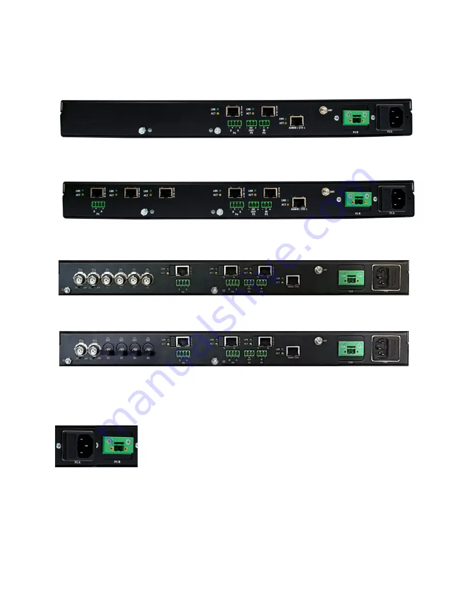
Examples of NTS 03-G+ back panels are shown (see Figure 12 - Figure 15). Their appearance will
vary when fiber Ethernet ports are fitted, or the fiber slave option is selected.
Figure 12 – Rear panel of NTS 03-G+, 3 Port Option
Figure 13 – Rear panel of NTS 03-G+, 6 Port Option
Figure 14 – Rear panel of NTS 03-G+, 4 Port with BNC IRIG-B outputs
Figure 15 – Rear panel of NTS 03-G+, 4 Port with ST fiber outputs
P1A / P1B: Power Input(s)
Power is applied to the unit via P1A and/or P1B (when fitted – dual
power supply option). The NTS 03-G+ can be ordered with high voltage
AC/DC supplies, high voltage DC supplies or medium voltage DC
supplies, or a combination. IEC-320 power connectors (shown to the
left – P1A) are used for high voltage AC or DC, and 5.08 mm 2-pin
connectors are used for low, medium or high voltage DC. The polarity of DC power sources is
not important as both the unit and case are isolated from the supply inputs. This enables the
use of positive earth, negative earth or fully floating DC power sources. If either of the power


