TTM 01-G Manual / October 2018
11
Installation
Identification
Each TTM 01-G unit is shipped with an identification label on the side of the case. The label provides details of
the optional output (if any), the power supply fitted to the unit, and the unit’s serial number.
Check the identification label on the side of the unit to ensure that the correct order code and voltage
range has been supplied before proceeding with the installation.
The label on the side of the TTM 01-G contains the voltage range: Do not apply power outside of this
range!
Location
The unit is intended for installation in restricted access areas. A restricted access area can be accessed
only using a lock and key or other means of security. Installation is to be done by suitably qualified
personnel.
Power Supply
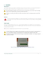
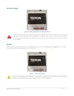
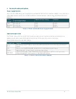
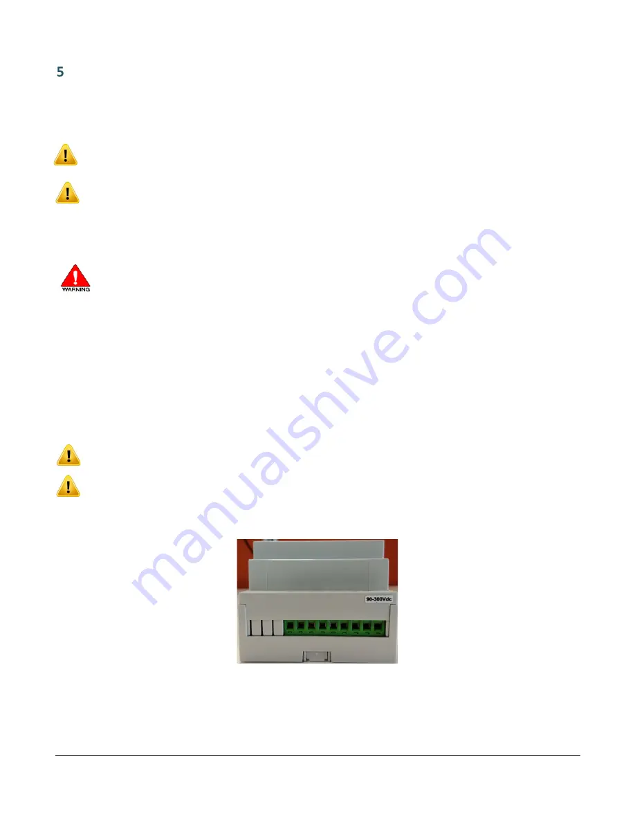
DC power should be applied to the ‘+’ and ‘-‘ screw clamp terminals above the “PWR” input. The DC polarity is
not critical. As shown in Figure 3, the input voltage range can be found on the side of the unit, above the power
input screw clamp terminals.
Note
: The Power supply has polarity protection built in to prevent damage.
The input voltage range is marked on the product label on the side of the unit, and on a label above the “+’
and ‘-“ screw clamp terminals on the power input. Do not apply voltage outside the range noted.
The label on the side of TTM 01-G indicates the type of output Option Card fitted: Do not apply voltages to
output only interfaces
!
Figure 3 - Power supply voltage input label above PWR screw clamps
Summary of Contents for TTM 01-G
Page 1: ...TTM 01 G USERMANUAL ...


