Kona Macro User Guide
T0004279_UG
Version 1.1
TEKTELIC Communications Inc.
Confidential
Page 14 of 34
1.
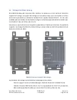
Bolt the wall mounting bracket to the Gateway module using the supplied bolts and
washers.
2.
While temporarily supporting the Gateway with bracket, install the two site supplied
pipe clamps, one through each of the upper and lower slotted clamp mounting points.
2.5
Ground Cable Installation
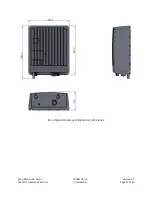
The Kona Macro Gateway is considered Permanently Connected Equipment and requires a
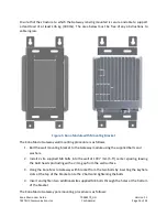
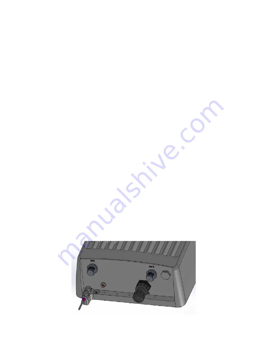
permanently connected Protective Earth Ground (PEG) conductor. The Protective Earth Ground
connection is made through a 1/4 x 0.75” on center double hole lug to the ground termination
point illustrated in Figure 6. The ground cable gauge shall be #10 AWG minimum.
The Kona Macro Gateway grounding system shall follow local and national electrical codes. The
Protective Earth Ground conductor terminated at the double hole lug point is mandatory and
must be the first connection made to the Kona Macro Gateway during installation. Proper
routing and termination of this cable is key to robust lightning withstand performance; in high
susceptibility installations, every effort shall be made to minimize connection inductance and
ground bed resistance.
The ground cable installation steps are as follows:
1.
Lightly abrade the surface of the casting ground area with a fine wire brush to remove
the oxide layer.
2.
Use a clean cloth to remove any debris from this surface.
3.
Immediately coat the contact surface with a thin layer of anti-oxidant compound.
4.
Install the ground cable through its 2-hole lug onto the chassis ground point using the
two supplied 1/4 - 20 x 1/2” bolts with flat and star lock washers, torqued to 10.4 Nm
(92 in·lbs).
Figure 6: Chassis Ground Connection


