background image

KONA Mega Gateway User Guide 

T0008387_UG 

Version 1.0 

TEKTELIC Communications Inc. 


Page 11 of 20 

2


Installation 

2.1


Safety Precautions 


Installation,  operation,  and  maintenance  of  the  KONA  Mega  Gateway  must  only  be 
performed by a professionally trained service technician who is aware of all hazards involved. 


The KONA Mega Gateway must be installed in a restricted access location (such that touching 
of the Gateway by non-service persons is not likely). 


The KONA Mega Gateway may become hot to the touch during normal operation at elevated 
ambient temperatures. The surface temperature of the Gateway may reach 90°C. 


The KONA Mega Gateway has no internal field serviceable parts. The Gateway module must 
only be opened by an approved TEKTELIC service center. 


All installation practices must be in accordance with the local and national electrical codes. 


Do not work on the system during periods of lightning activity. 


The KONA Mega Gateway is considered permanently connected equipment. The Protective 
Earth Ground connection (that is, the two-hole lug to chassis ground) is always required. 


Ensure the KONA Mega Gateway Protective Earth Ground connection is properly terminated 
prior to the connection of any other interfaces. 


The  KONA  Mega  Gateway  contains  primary  lightning  surge  suppression  on  the  Direct  DC 
power port, the Copper Ethernet port, the GPS antenna port and the LoRa RF antenna ports. 
The primary lightning protectors have the ability to bridge the interface isolation boundary 
during over-voltages. Ensure that the Protective Earth Ground connection is always in place. 


Ensure that the KONA Mega Gateway, its antennas and supporting structures are properly 
secured  to  eliminate  any  physical  hazard  to  people  or  property.  The  Gateway  must  be 
securely mounted according to the mounting instructions prior to any cable connection and 
operation. 


The KONA Mega Gateway does not contain a power supply disconnection device; a readily 
accessible disconnection device must be incorporated external to the KONA Mega Gateway. 


The direct DC powered KONA Mega Gateway shall be supplied through an input overcurrent 
protection  device  rated  not  more  than  10  A.  The  overcurrent  protection  must  have  the 
appropriate current interrupt capacity for the power source and must be incorporated into 
the non-earthed conductor(s) of the KONA Mega Gateway DC supply. 

Summary of Contents for T0004978

Page 1: ...hts reserved All products names and services are trademarks and registered trademarks of their respective companies KONA MEGA GATEWAY 900MHZ TDD User Guide Document Type User Guide Document Number T0008387_UG Document Issue 1 0 Document Status Approved Product Name KONA Mega Gateway Product Code See Table 1 Issue Date October 14 2022 ...

Page 2: ...ide T0008387_UG Version 1 0 TEKTELIC Communications Inc Page 2 of 20 Document Revision Revision Issue Date Status Editor Comments 0 1 Oct 12 2022 Draft K Minderhoud Original Draft 1 0 Oct 14 2022 Released K Minderhoud Approved ...

Page 3: ...nstallation 11 2 1 Safety Precautions 11 2 2 Unpacking and Inspection 12 2 3 Required Equipment for Installation 12 2 4 KONA Mega Gateway Mounting 12 2 5 Ground Cable Installation 14 2 6 Direct DC Power Cable Installation 15 2 7 RF Cable Installation 16 2 8 Antenna Installation 16 2 9 Copper Ethernet Cable Installation 17 3 Radio Compliance Statements 18 4 Déclarations de conformité à la radio 20 ...

Page 4: ...G Version 1 0 TEKTELIC Communications Inc Page 4 of 20 List of Tables Table 1 KONA Mega Gateway Models 6 Table 2 KONA Mega Gateway Interface Connector Types 10 Table 3 KONA Mega Gateway Specifications 10 Table 4 Maximum 3G 4G antenna gain 16 ...

Page 5: ...ctor Bulkhead Field 8 Figure 3 KONA Mega Gateway Option 2 with Circular Plastic Connector Bulkhead Field 8 Figure 4 KONA Mega Gateway Option 3 with Circular Plastic Connector Bulkhead Field 9 Figure 5 KONA Mega Gateway Option 4 with Circular Plastic Connector Bulkhead Field 9 Figure 6 KONA Module with Mounting Bracket 13 Figure 7 Chassis Ground Connection 14 Figure 8 Direct DC Power CPC Connector ...

Page 6: ... and backhaul options including copper Ethernet and 3G 4G wireless This user guide is specific to a subset of the full KONA Mega portfolio inclusive only of Mega gateways employing Time Division Duplexing TDD operating in the 900MHz frequency band and optionally including the Sierra Wireless EM7455 3G 4G modem Table 1 lists all such KONA Mega Gateway models Table 1 KONA Mega Gateway Models Product...

Page 7: ...EKTELIC Communications Inc Page 7 of 20 Figure 1 illustrates the common Gateway external form factor The differences between the options are limited to the bulkhead field and the internal cavity bandpass filters Figure 1 KONA Mega Gateway Common Dimensions ...

Page 8: ... bulkhead component fields are detailed in the following figures Figure 2 KONA Mega Gateway Option 1 with Circular Plastic Connector Bulkhead Field Figure 3 KONA Mega Gateway Option 2 with Circular Plastic Connector Bulkhead Field GPS Antenna LoRa RF Antenna 0 Enclosure Vent LED Protective Earth Ground Copper Ethernet LTE Antenna Port ...

Page 9: ...ircular Plastic Connector Bulkhead Field All KONA Gateway module interconnect is located on the bottom facing bulkhead The RF connectors are waterproof while unmated but all other connectors must be terminated with mating connectors or covered with the supplied protective cap when not in use in order to be water tight Connector types and their mating connectors are listed in Table 2 LoRa RF Antenn...

Page 10: ...teway specifications are listed in Table 3 Table 3 KONA Mega Gateway Specifications Attribute Specification Dimensions 222 2mm 8 7 wide x 101mm 4 0 deep x 287 3mm 11 3 tall Weight 5 1 kg 11 3 lbs Operating Temperature 40 C to 60 C 40 F to 140 F at sea level Including solar loading Relative Humidity 10 to 100 Operating Altitude 60 m to 4 000 m 197 ft to 13 123 ft Power Input Direct DC 48 VDC nomina...

Page 11: ...s required Ensure the KONA Mega Gateway Protective Earth Ground connection is properly terminated prior to the connection of any other interfaces The KONA Mega Gateway contains primary lightning surge suppression on the Direct DC power port the Copper Ethernet port the GPS antenna port and the LoRa RF antenna ports The primary lightning protectors have the ability to bridge the interface isolation...

Page 12: ...o not discard the shipping box or foam inserts as they will be required if a unit is returned for repair or re configuration 2 3 Required Equipment for Installation The following tools are required to install the KONA Mega Gateway module 1 A 6 point metric socket set and torque wrench drive 2 Anti oxidant compound NO OX ID Penetrox Noalox Ox Gard or equivalent 3 A small wire brush 4 A clean cloth ...

Page 13: ... is as follows 1 Bolt the wall mounting bracket to the Gateway module using the supplied bolts and washers 2 Install 2 site supplied M8 bolts into the wall at 139 7 mm 5 5 center spacing leaving the bold heads protruding with a 2mm gap from the wall surface 3 Hang the KONA Mega Gateway with bracket from the two bolts by inserting the keyhole slots at the top of the bracket onto the 2 bolts and tig...

Page 14: ...stem shall follow local and national electrical codes The Protective Earth Ground conductor terminated at the double hole lug point is mandatory and must be the first connection made to the KONA Mega Gateway during installation Proper routing and termination of this cable is key to robust lightning withstand performance in high susceptibility installations every effort shall be made to minimize co...

Page 15: ...ssis earth with the exception of the primary surge suppressors One lead of the DC power feed is normally earth referenced external to the KONA Mega Gateway usually at the power source by convention The DC power cable shall be rated for outdoor application and in accordance with local and national electrical codes The CPC DC connector shall be as specified in Table 2 and shall follow the signal pol...

Page 16: ...teway module or if remotely located an external surge suppressor must be provisioned 2 8 Antenna Installation Note Installation operation and maintenance of the KONA Mega Gateway must only be performed by a professionally trained service technician who is aware of all hazards involved Maximum gain for LoRa antenna s of 8dBi if the cable insertion loss at 900 MHz is 0 5dB or more for 1 carrier oper...

Page 17: ...ioning and maintenance or may be permanently connected for backhaul When the port is not in use the weatherproof protective cap must be installed When the port is permanently connected for backhaul a proper water tight mating connector specified in Table 2 must be used The Ethernet cable must have minimum 24 AWG conductors and shall be rated for outdoor application according to local and national ...

Page 18: ... Consult the dealer or an experienced radio TV technician for help To comply with FCC IC RF exposure limits for general population uncontrolled exposure the antennas used for this transmitter must be installed to provide a separation distance of at least 80 cm from all persons and must not be co located or operating in conjunction with any other antenna or transmitter Industry Canada This Device c...

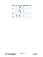
Page 19: ...Technology Band Frequency MHz Maximum Antenna Gain dBi LTE 2 1850 1910 3 0 4 1710 1755 6 0 5 824 849 3 0 13 777 787 6 0 17 704 716 6 0 25 1850 1915 3 0 UMTS 2 1850 1910 3 0 4 1710 1755 6 0 5 824 849 3 0 GSM 850 824 849 3 0 1900 1850 1910 3 0 CDMA BC0 824 849 3 0 BC1 1850 1910 3 0 BC10 817 824 3 0 ...

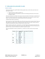
Page 20: ...e une antenne avec un gain maximal de 8dBi peut être utilisée pour les radios LoRa de ce produit si la perte d insertion de câble à 900 MHz est de 0 5dB ou plus pour une opération de porteuse à 28 0 dBm Une ou plusieurs antennes doivent être installées à un emplacement situé à au moins 31 5 pouces 80 cm de tout corps humain Pendant le fonctionnement du produit conservez toujours une distance de sé...

Reviews: