background image

ME

ME

ME

ME Series

Series

Series

Series Printer

Printer

Printer

Printer Operation

Operation

Operation

Operation Manual

Manual

Manual

Manual

- 69 -

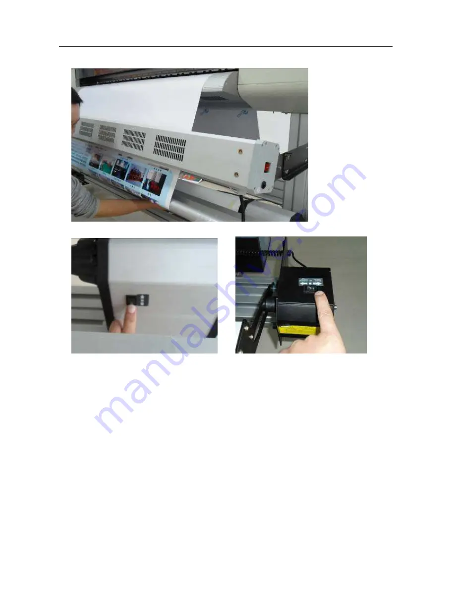
7.3.3

Put the tension bar down

7.3.4 Switch on take up

system, select

winding

direction.

Summary of Contents for ME1301

Page 1: ...Oct 10 2012 VE Series Printer Operation Manual 600T00120 Primary Edition Version 1 0 ...

Page 2: ...ot allow small children to touch the printer The following describes are important points for safe operation Be sure to observe them strictly Conventions used in this manual To ensure the safe and correct use of the printer as well as to prevent human injury and property damage the safety precautions provided in this manual are ranked in the three categories described below Be sure to gain a full ...

Page 3: ... to a lot of vibration Such locations may cause the printer to tip over and cause injuries Do not place heavy objects on top of the printer Such objects may tip over or fall off causing injuries If the printer is mounted on its dedicated stand be sure to use the caster stoppers to fix the stand in place and prevent it from moving while the printer is being used If the stand is not fixed in place t...

Page 4: ...ay result in a fire hazard or short circuit Do not use a power cable other than the one supplied with your printer Use of a different power cable may result in a fire hazard or short circuit Be careful of the following when connecting a ground wire Items which allow connection to a ground wire Ground terminals of electric outlets Ground terminals after completion of grounding work type D Items whi...

Page 5: ...agnetic interference Such as reproducers and cordless telephones Do not use damaged or attrited power cable Handling precautions WARNING Do not disassemble or modify printer If the printer makes an unusual noise generates smoke overheats emits a strange odor or otherwise functions abnormally immediately turn off the power remove the plug from the power outlet and either contact the store where you...

Page 6: ...ntenance staff to maintain power cables or plug have be damaged liquid splashing into the printer printer fall down or damaged Printer is not in normal operation or performance are changed obviously Maintenance and inspection precautions WARNING Be sure to turn off the power and remove the power plug from the power outlet before performing any cleaning operations Failure to do so may result in a f...

Page 7: ...ink may cause damage to the surface coating of this printer CAUTION As a safety precaution store the print heads and ink cartridges in a location out of the reach of small children If ink is licked or ingested accidentally consult a doctor immediately Do not use any ink other than those specified because it may not only disturb printing quality but also cause a malfunction which will prevent appro...

Page 8: ...d 23 2 7 Ink Initializing 25 2 8 Turn On Pinter 27 2 9 Load Media and Nozzle Checking 28 Chapter 3 Control Panel Parameter Setting 3 1 Control Panel 32 3 2 Manu Tree 33 3 3 Manu Description 35 Chapter 4 Software Operation Instruction 4 1 Software Instruction 38 4 2 Operation Procedure 38 4 2 1 Install RIP and Printer Set up 38 4 2 2 Print Task and Image Edit 42 4 2 3 Print Mode and Parameter Setti...

Page 9: ...nual Manual 8 6 2 Operation Diagram 62 6 3 Features 62 6 4 Structure and Description 63 Chapter 7 Media Take up System Optional 7 1 Instruction 65 7 2 Structures 65 7 3 Operation Description 66 Chapter 8 Maintenance 8 1 Daily maintenance 68 8 2 Linear Rail maintenance 68 8 3 Pint head maintenance 68 8 4 Ink supply maintenance 69 ...

Page 10: ...ard 220ml 2 4 color Optional 220ml 8 color Media Type PP Photo Paper Lamp Pieces PVC Vinyl Mesh Banner Media Release Standard Passive Release Optional Auto feeding Take up Maximum Media Width 1640mm Maximum Media Wight 30kg Print Head Height 1 5mm 3 0mm Adjustable Head Clean Capping Auto cleaning Capping system Media Heater Front Real Constant Temperature control Printing Platen Adjustable Media D...

Page 11: ...ent and printing quality 3 Right Cover Open this cover to check head cleaning and capping station 4 Press handle To be used for releasing and loading media 5 Media taking up Holder To holder the paper core for rewinding the media after printing 6 Front Media Guide This is the guide for media exiting and drying after printing 7 Media Drier This is used for drying media after printing 8 Waste Ink Bo...

Page 12: ... Operation Operation Manual Manual Manual Manual 11 1 2 3 Item Description Function 1 Rear Media Guide This is the guide for media feeding and pre heating 2 Ink Cartridge This is the bulk ink storage for ink supplying 3 Media Release Holder This is media holder for passive release 1 2 3 4 5 6 ...

Page 13: ...oard and print head 2 Print Head This is print head DX5 3 Damper This is a damper for ink storage and absorb the pressure fluctuation while carriage moving 4 Ink Tube Connector This is used to connect damper and ink tube 5 Damper Holder This is a clip to hold the damper and avoid it loose during carriage moving 6 Head Height Adjust Handle This is used to adjust the head height There are 3 position...

Page 14: ...s the chain for holding cables and ink tubes 1 2 3 4 5 6 7 8 9 10 11 Item Description Function 1 Power Cord Socket This is the socket for supplying electrical power from the power source 2 Heater controller This is a digital controller for control the Printing Platen temperature 3 Main Power Switch This is main switch for turn on off the printer 4 Front Media Guide heater switch This is a switch f...

Page 15: ...nual 14 Chapter 2 Installation Guide Read the safety guide more carefully before install the printer 2 1 Open Package and Remove Printer DANGER Be careful while use fork lift to remove printer from the packaging 2 1 1 Open the wooden box 2 1 2 Remove the modules 2 1 3 Remove printer Remove all side plate of wooden box as the fig below ...

Page 16: ...rinter Printer Printer Printer Operation Operation Operation Operation Manual Manual Manual Manual 15 Remove fixing screws on the pallet 2 1 4 Remove 4 screw nuts lift printer up Remove shipping bracket fixing screws and remove Orange brackets ...

Page 17: ...king List Check the items on the list Please contact seller if there is any thing missing Item Description Qty Item Description Qty 1 RIP Software 1 2 Power Cord 1 Item Description Qty Item Description Qty 3 USB Cable 1 4 Print Head Cable 2 5 Tier 10 6 Print Head 1 7 220ml Ink Cartridge 8 8 Waste Ink Tank Holder 1 9 Warranty Card 1 10 Quality Certificate 1 ...

Page 18: ...es Printer Printer Printer Printer Operation Operation Operation Operation Manual Manual Manual Manual 17 11 Operation Manual 1 12 Quick Start Instruction 1 13 Waste Ink Tank 5L 1 14 Glove Pack 1 15 Injector 1 16 Funnel 4 17 Clean Stick 4 ...

Page 19: ...al Manual 18 2 3 Install Printer WARNING Two person required when install printer 2 3 1 Install Leg Assembly Take leg parts from the packaging Take low support beam insert the fixing screw on the end of beam into fixing hole on the legs Fixing the beam by 6 pcs of M6X16 Hex screws see below fig Do the same for another side of leg ...

Page 20: ...ersons to do the procedure is necessary With the help of fork lift put the printer on the stand and fix it by 4 pieces of M6X18 Hex screws in each side Please be sure that the fixing screw on the top of the leg is inserted in to the fixing hole in low beam of printer See the picture below 2 4 Install Drier WARNING Two people required while install the drier 2 4 1 Install Drier Bracket Take the bra...

Page 21: ...eration Operation Manual Manual Manual Manual 20 Install the bracket Make sure two brackets in both side are in the same level 2 4 2 Install Drier Assembly Install the drier on the bracket and fix it by two screws Do the same way for another side Remove two M5X12 Hex Screws in both side of drier ...

Page 22: ...ation Operation Operation Operation Manual Manual Manual Manual 21 The hot air direction is adjustable as follow Use Hex screw driver to loose the fixing screw in both side turn the drier to a certain angle then fasten the screw After installation Turn the drier to proper angle ...

Page 23: ...l Manual Manual Manual 22 2 5 Install Waste Ink Tank Holder Take the waste ink tank holder and install it on right side of leg assembly Remove two screws on the leg Install waste ink tank holder on the right side leg Fix it by 4 pcs of M6X16 Hex screws Push the holder down to the end and fix it by two M8X14 Hex screws ...

Page 24: ...int Head 2 6 1 Connect flat cables to print head Make sure the cable are in the right direction See below fig The blue color of two cables have to be faced each other Recommend to use same width paper to cover the connector to avoid circuit short by sprayed ink 2 6 2 Use two M3X6 Hex screws to fix print head on holding plate See the fig below 3 fixing holes ...

Page 25: ...ion Operation Manual Manual Manual Manual 24 2 6 3 put the head assembly on the carriage and fix it by 3 pcs of M X6 Hex screws on head plate 2 6 4 Install head adjustment screw Note The screws are used to adjust the straightness of the head Fix the head on the plate by using 3 pcs of M3X6Hex screws ...

Page 26: ...oard 2 7 Ink Initializing 2 7 1 Insert 8 empty cartridges into the slots 2 7 2 Remove rubber cap on each cartridge fill the ink in to the cartridge by using funnel Please make sure the ink color should be match with the marks on the cartridge Please be sure the ink level should be within the level limit lines on the cartridge Note while the ink level is below the low limit line of the cartridge th...

Page 27: ...t the injector with the damper draw the ink out from the cartridge into the damper Note the ink level in the damper should be not less than 50 otherwise it will cause ink interrupted during printing 2 7 4 Connect each damper to individual ink inlet on print head Note please make sure the color order should be in correct K K C C Y Y M M from left to right ...

Page 28: ... power supply as per the requirement otherwise may damage the equipment 2 Please remove any un necessary remains in the printer before switch on power 3 Connect printer and heater to power supply by two power cords 2 8 2 Booting printer and self checking Note Please move the carriage and check the gap between the head and printing plate by manually Make sure there is no substance on the platen Mak...

Page 29: ...al Manual 28 2 9 Load Media and Nozzle Checking 2 9 1 put the media on the holder and fix well Note the holder can fit 3 inch paper core or 2 inch paper core by removing the core adapter see below This is the holder for 3 in paper core Push the clips in for position remove 3 in core adaptor Now the holder will fit 2 in paper core ...

Page 30: ...ide holder on low support beam move anther holder to fit media core 2 9 2 Lift press roller by push back Press Handle Put the media going through press roller Pull and smooth the media equably from the front of printer Pull back the handle to release press roller Push the holder then fasten the fixing screw Make sure the media is on the platen smoothly ...

Page 31: ...d the display will back to Main Manu Press Nozzle Check the carriage will move left and a nozzle status bar will be printed Observe each nozzle status and do clean process again if necessary Note if there still have some nozzles don t jetting well please stop clean and do some printing for while then do the clean process again While all process is done the machine is ready to run for further adjus...

Page 32: ...button to enter the main Manu 3 Nozzle Checking Press this button to do nozzle checking print 4 On Line Press this button for linking the PC 5 Left Press this button for reduce the value or move the carriage left toward 6 Up Press this button to go up on displayed Manu Or move the media in backward 7 OK Press this bottom to confirm for next step 8 Down Press this bottom for choose next item on the...

Page 33: ...2 Margin_Set 3 Media_Detect 2 Head_Clean 1 Heavy_Mode 2 Std_Mode 3 Light_Mode 4 Cap_Clean 5 Capping 3 Param_Set 1 Wiper_Pos 2 Wiper_Cycle 3 Carriage_Spd 4 Vacuum_Adj 5 Auto_Purge 6 Auto_Clean 7 Vacuum_Mode 4 System_Set 1 Head_Qty 2 LCD_Cntrst 3 Language 4 Media_Detect 5 Cutter_Enab 6 Media_End 7 Load_Default 8 About 5 Engr_Mode 1 Motion_Test 2 Speed 3 Print_Width 4 PurgePosition 5 Voltage_Adj ...

Page 34: ...n position Press Exit to back Media_detect Lighten this item by using Up or Down kay press OK to confirm the carriage will move left to detect the paper edges then record the paper width this function is not available for this printer Head_Clean Heavy_Mode Lighten this item by using Up or Down Key press OK key to confirm The printer starts head clean process automatically The clean time is longer ...

Page 35: ...one by service engineer while the wiper is worn out and change Wiper_Cycle Lighten this item press OK to confirm The number displayed indicates the times the wiper wipes the head after cleaning Use Left or Right key to change the number The range is 1 to 3 The default is 1 Mean the wiper wipes one time after cleaning This procedure is done by service engineer only Carriage_Spd Lighten this item pr...

Page 36: ...f if there is no printing task existed 2 Enabl The vacuum is generated while the printer is on 3 Disab There is always no vacuum on the platen Syetem_Set Head_Qty Lighten this item press OK to confirm Use Left or Right key to choose the head number 1 indicates that one head is used 2 indicates that two head are used The default number is 1 LCD_Cntrst Lighten this item press OK to confirm Use Left ...

Page 37: ...peat This is used for carriage moving test Speed Lighten this item press OK to confirm This is used to set up the value of printing speed Use Up or Down key to choose mode use Left and right key to change the value The bigger number indicates the carriage moves faster 9 is the default value of Prod mode 6 is default number of Fine mode Press OK key to confirm the setting and back Print_Width This ...

Page 38: ...on Operation Manual Manual Manual Manual 37 there is a minor difference for different type of ink Lighten this item press OK to confirm use Up and Down key to change the value The range is 0 to 3 For water based ink the default value is 0 For eco solvent ink the default value is 1 7 Press OK to back ...

Page 39: ...ration Environment Hardware CPU Intel Pentium4 and above 2GHZ 1G Memory Display Resolution 1024X768 and above Operation System Windows2000 XP WIN7 4 2 Operation Procedure 4 2 1 Install RIP and Printer Set up 1 Insert MainTop CD into driver the program will be auto run and display as below 2 Click MAINTOP DTP Note The system recommends to install the software in default route Restart computer after...

Page 40: ...ME ME ME ME Series Series Series Series Printer Printer Printer Printer Operation Operation Operation Operation Manual Manual Manual Manual 39 ...

Page 41: ...tion Operation Operation Manual Manual Manual Manual 40 3 Start the program Refer to follow fig Note Please make sure the MainTop RIP Dongle is inserted in USB port otherwise the follow massage will be displayed 4 Open RIP software and make printer setting Click File choose Printer Setup ...

Page 42: ...ME ME ME ME Series Series Series Series Printer Printer Printer Printer Operation Operation Operation Operation Manual Manual Manual Manual 41 Click Install Choose TEKTRON in Printer Type list ...

Page 43: ... Manual Manual Manual Manual 42 Choose Printer Name ME1601 E for example Click OK back to precious Manu Click Set As Default Printer 4 2 2 Print Task and Image Edit 1 Create a new print task Click New refer to below 2 Set printing media width Click Custom under Page Here we set the width as 1600mm the length is ...

Page 44: ...ME ME ME ME Series Series Series Series Printer Printer Printer Printer Operation Operation Operation Operation Manual Manual Manual Manual 43 1000mm for example ...

Page 45: ...s Series Printer Printer Printer Printer Operation Operation Operation Operation Manual Manual Manual Manual 44 3 Load the image Click Load Image shortcut Choose the image from the file Choose Off under Page of Image Picture Setting ...

Page 46: ...Operation Operation Manual Manual Manual Manual 45 4 2 3 Print Mode and Parameter Setting 1 After finish image editing click Printer to set up print parameter The below dialogue window displays Please refer to RIP user manual for detailed instruction The operator can keep default parameter set ...

Page 47: ...ion Operation Manual Manual Manual Manual 46 Click Properties below window will be displayed Choose ICC profile The Pinter Ports is Tektron Select print resolution V360X1080DPI 3PASS Production Mode V720X720DPI 4PASS Standard Mode V720X1080DPI 6PASS Quality Mode V720X1440DPI 8PASS High Quality Mode ...

Page 48: ...n Operation Operation Manual Manual Manual Manual 47 Click Auto the system would recall the media size while image size edited In example the window will show Customized 1600mmX1000mm Choose ICC Profile Note ICC profile shall match with the resolution selected The default media size is Auto ...

Page 49: ...ge One method is that the system will convert the image into RIPed format then print Click Print To File the software starts to convert the image As the image data has been converted in RIPed file before print so while the printer prints a RIPed file the printer would not be interrupted and wait the data processed by the PC The disadvantage is the printer is not printing the image in real time The...

Page 50: ...ries Series Series Printer Printer Printer Printer Operation Operation Operation Operation Manual Manual Manual Manual 49 Anther method is real print Click OK the system will transfer the data to Print Manager see below fig ...

Page 51: ...ed Print Management System while RIPing 4 2 4 Printing Management System 1 when set Printing Management System first time the operator has to use Real Print method to open Printing Management System otherwise Printing Manager will not find Tektron Printer Port See follow 2 Printing Management System Please refer to MainTop User Manual for further information The Printing Management System is showe...

Page 52: ... and lighten the task then click print button the printing will start Progress Status Bar The data format is AA BBB BBB indicates the date volume has been transferred to Printing Management System AA indicates the data volume that being transferred to printer through USB Tips if there is no progress data indicates that mean there is problem in data transition You can re start Printing Management S...

Page 53: ... ME Series Series Series Series Printer Printer Printer Printer Operation Operation Operation Operation Manual Manual Manual Manual 52 4 3 Printer Property Click Printer Property shortcut Set Printer Parameter ...

Page 54: ...e Line Mode This is regular printing mode without discount of speed Wave Mode This is a wave processing method applied on each printing pass to recover the image problem banding caused by missing stepping or nozzle clogged The printing productivity will be lower than normal Feather Mode This is a feather processing method applied on each printing pass to recover the image problem banding caused by...

Page 55: ... checking the head if there is any slant 2 Media Feeding Calibration Print test image for different pass mode to verify stepping parameter 3 Media Choose The calibration parameter might be variable for different media Once finish a calibration save the data on the name of the media used recall the file before print on this type of media in the future 4 Bid Calibration Print the checking chart for ...

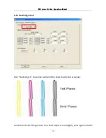
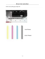
Page 56: ...nter Printer Operation Operation Operation Operation Manual Manual Manual Manual 55 Print Head Alignment Click Slant Adjust the printer will print the head check chart as below Loose three head fixing screws turn head adjust screw slightly print again until the ...

Page 57: ...ME ME ME ME Series Series Series Series Printer Printer Printer Printer Operation Operation Operation Operation Manual Manual Manual Manual 56 line for each printing pass align well ...

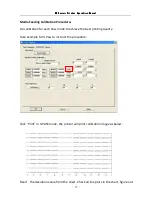
Page 58: ...al Manual 57 Media Feeding Calibration Procedure Do calibration for each Pass mode to achieve the best printing quality Take example for 4 Pass to instruct the procedure Click Print in 4 PASS mode the printer will print calibration image as below Read the deviation value from the chart Check all line pairs in the chart figure out ...

Page 59: ...al Manual Manual Manual 58 the number under the most matched line pairs which is the value to be fill in calibration Click 4Pass the widow displays as below Fill the value read in the chart assume the value is 4 for example to offset window click OK to save and back to previous Manu Bi direction calibration procedure ...

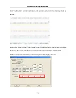
Page 60: ...anual 59 Click Calibration on Bid calibration the printer will print the checking chart as below Look at the chart printed find the each line of individual color that is most matching black line the value under the line is the deviation to be filled in related color Fill the value to the window for each color then click Apply to save ...

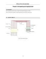
Page 61: ...on Manual Manual Manual Manual 60 Chapter 5 Ink Supplying and Capping System 5 1 Introduction The ink supplying is nature siphonic method from the bulk cartridge to print head There are three clean methods for head cleaning that can be selected during printing 5 2 Operation Diagram Fig 5 1 Clean System Diagram ...

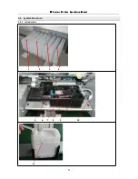
Page 62: ... ME ME ME Series Series Series Series Printer Printer Printer Printer Operation Operation Operation Operation Manual Manual Manual Manual 61 5 3 System Structure 5 3 1 Introduction 1 2 3 4 5 6 7 8 9 10 11 ...

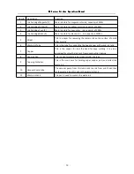
Page 63: ...20ML 5 Wiper This is a wiper for removing the remain ink on the surface of nozzle after purging 6 Waste Ink Tube This is the tube for connecting the head capper with waste ink tank 7 Capper This is the capper for seal the head for keep wetting It is also a container for store the ink such from nozzle while cleaning 8 Capping Pad This is a pad for waste ink or clean solution storage 9 Capping Conta...

Page 64: ...or particular media to achieve the best printing results 6 2 Operation Diagram Fig 6 1 Heating System Diagram 6 3 Features The front and rear heater are constant temperature controlled The printing platen heater s temperature is controlled by a separate PID controller The user can set the temperature as required All of the heater has a over heating protection for 70 C the power will be switched of...

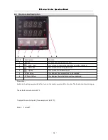
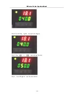
Page 65: ... used to change the digit that would be changed 3 Down key This is used for reducing the count 4 Up key This is used for increase count 5 SV Set Value This displays the temperature to be reached 6 PV Presnt Value This displays the actual temperature measured Procedure Switch on heater power switch after turn on the main power switch of printer The heater starts warming up The default control point...

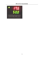
Page 66: ...nter Printer Printer Printer Operation Operation Operation Operation Manual Manual Manual Manual 65 Step 2 Press shift key Lighten the digit to be changed Step 3 Press or key to change the value Step 4 Press SET again to save the value and exit ...

Page 67: ...ME ME ME ME Series Series Series Series Printer Printer Printer Printer Operation Operation Operation Operation Manual Manual Manual Manual 66 ...

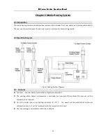
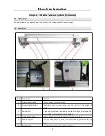
Page 68: ...tion Function 1 Passive Media Holder This is a holder for fix the media 2 Supporting Slot Guide The holder can be moved along with the slot to fit the length of media 3 Tension Bar It give the media take up system a constant tension and also give the sensor signal for media auto control system 4 Active Media Holder This is a holder driven by DC motor for media rewinding 5 Take up support This is a...

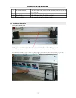
Page 69: ...system by manual or by sensor to auto control 8 Power Cord This is the power card for taking up system 9 Direction Switch This is used to change the winding direction 7 3 Operation Description 7 3 1 Install Paper Core Install paper core stick a double side adhesive in horizontal on the surface of the paper core 7 3 2 Pull the media to paper core equably slight press the media and stick it on paper...

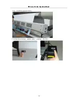
Page 70: ...ries Series Series Series Printer Printer Printer Printer Operation Operation Operation Operation Manual Manual Manual Manual 69 7 3 3 Put the tension bar down 7 3 4 Switch on take up system select winding direction ...

Page 71: ...wer socket and USB connector Check the tension of X Y driving belt Do adjustment if necessary Check the tension of carriage driving belt Do adjustment if necessary Check the status of encoding strip Clean the dust on the strip if necessary Check press roller and pinch roll Clean the gap to keep the roll turning freely Check media guide slot Clean the slot to keep guide moving freely 8 1 3 Monthly ...

Page 72: ...e of the head be tried out Apply flush solution on the pad of head capper Initial head capping procedure to park the head on clean station If more than four days not using disconnect the damper from the head flush the head by using flush solution Initial capping procedure Unload print head Do as follows when you are going to unload print head Suck the ink out from print head and clean it with flus...

Reviews: