Operating Basics
14
P7350 5 GHz Differential Probe Instruction Manual
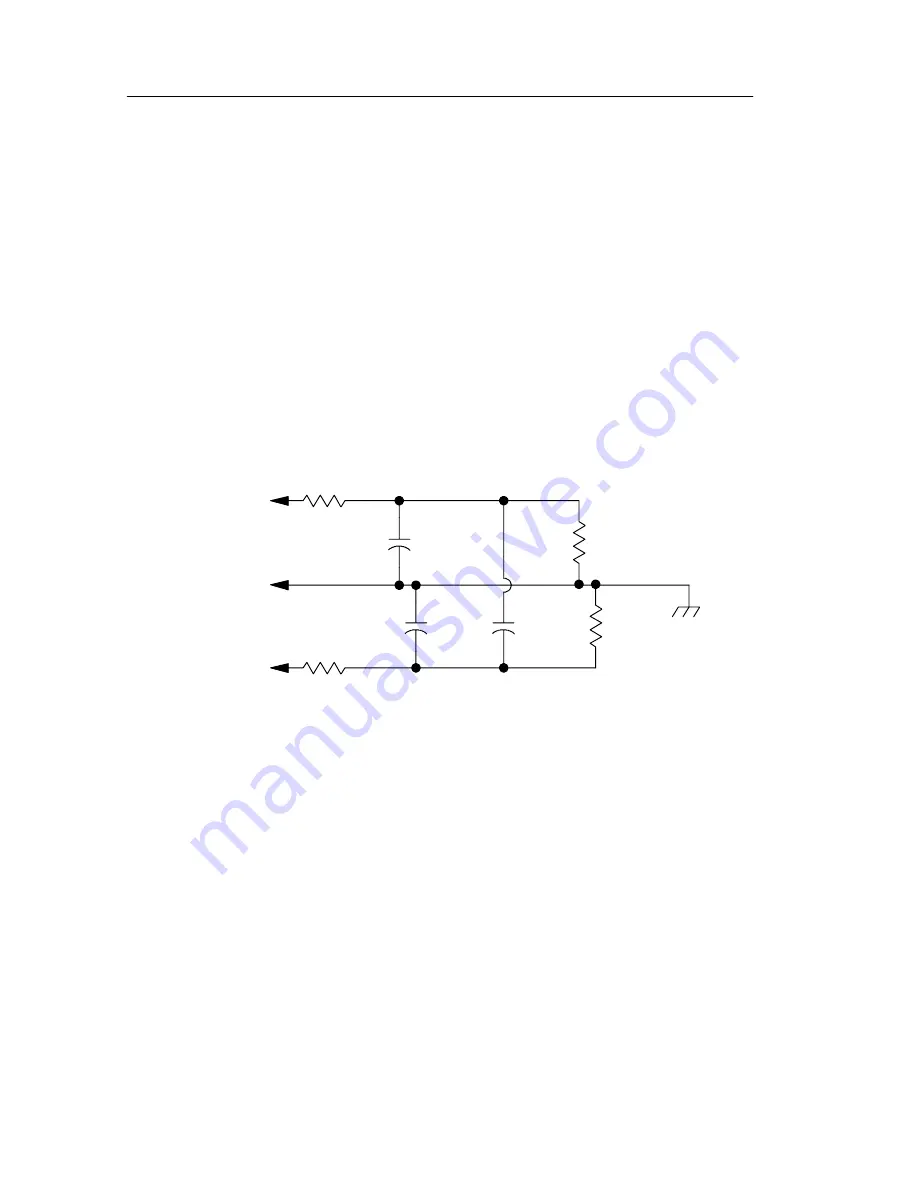
Input Impedance and Probe Loading
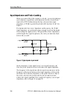
When you connect the probe inputs to a circuit, you are introducing a
new resistance, capacitance, and inductance into the circuit. Each
input of the P7350 differential probe has a characteristic input
impedance of 50 k
Ω
to ground in parallel with less than 0.4 pF. See
Figure 7.
For signals with low source impedance and frequency, the 50 k
Ω
input impedance on each input is large enough to prevent the inputs
from loading the signal sources. The greater the source impedances
and the higher the signal frequencies, the more you must take these
factors into account.
Input
0.1 pF
0.4 pF
0.4 pF
50 k
Ω
50 k
Ω
Ground
+
-- Input
130
Ω
130
Ω
Figure 7: Typical probe input model
As the impedance of the signal source on an input increases, the
more the probe loads the source and reduces the signal amplitude.
The frequency of the signal also affects signal measurement. As the
frequency of the signal increases, the input impedance of the probe
decreases. The lower the impedance of the probe relative to that of
the source, the more the probe loads the circuit under test and
reduces the signal amplitude. For a graph of frequency versus input
impedance, refer to Figure 13 on page 25.


