Operating
Instructions—7A42
EXT
CLOCK INPUT
The
EXT
CLOCK
INPUT
is
directly
compatible
with
either
TTL
or
ECL logic
families. The
instrument is
shipped from
the
factory
in
the
TTL
mode.
To
determine which
mode
is
selected
(ECL
or
TTL),
proceed
as
follows:
1.
Remove any
input
signal from
the
EXT
CLOCK
INPUT.
2.
Press
the
PROG
pushbutton
so
that
it
is
lit
green.
3.
Press
the
CLEAR
pushbutton,
to
eliminate
any
existing
TRIGGER
FUNCTION.
4.
Press
the
TRIG
VIEW
pushbutton so that
the
pushbutton
light
is
on
and
the
trigger
view
trace
is
displayed
on
the
mainframe
crt.
5.
Observe
the
trigger
view
trace
as
the
EXT
CLOCK
SYNC
pushbutton
is
pressed.
If
the trigger
view
trace
moves
upward
approximately
half
a
division
(when
the
EXT
CLOCK
SYNC
push-button
is
lit)
the
selected
mode
is
TTL.
If
the
trigger
View
trace
does
not
shift,
the
mode
is
ECL.
To
select
the
ECL
mode refer
qualified
service
personnel
to
the
7A42
Service
Manual.
The
EXT
CLOCK
INPUT
can
be
used
with
a
1X
probe
in
TTL
mode,
or
can
be
directly connected
to
the
logic
circuit
in
either
TTL
or
ECL mode;
10X
probes
should
not
be used
with
this input.
RESET
INPUT
The
RESET
INPUT
allows
the
operator
to
apply
a
signal
to
inhibit
the
trigger
output.
Applying
a
positive
0.8
volt
level
to
the
RESET
input
will
prevent
the
programmed
TRIGGER
FUNCTION
from
being
recognized
as
true.
The
result
is
that
no
trigger
output
signal
will
occur
until
the
reset
voltage
is
removed.
If
the
A
THEN
B nested-trigger
mode
is
selected,
TRIGGER
FUNCTION
A has
occurred,
and
TRIGGER
FUNCTION
B
has
not
occurred;
the
RESET
signal
will
reset
function A
(the
armed
condition)
as
well
as
inhibit
function
B.
Therefore,
the
RESET
input
can
be
used
to
enhance
the
A THEN
B
nested
trigger
operation
by
providing
an
"A
THEN
B
unless
RESET
”
feature.
TRIGGER
OUT
The
TRIGGER
OUT bnc
connector
is a trigger
output
signal
source.
This
signal
can
be
used
to
synchronize
other
equipment
with
the
7A42
TRIGGER
FUNCTION.
The
output
of
the
TRIGGER
FUNCTION is
determined
by the setting
of
the
A,
B,
or
A
THEN
B
pushbuttons,
the
programming
of
the
A
and
B
functions,
and
the
channel
input
signals.
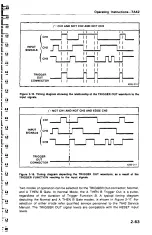
Timing
diagrams
for
a
typical
set
of conditions
are
shown
in
Figures
2-15
and
2-16.
2-62


