Operating
Instructions—7A42
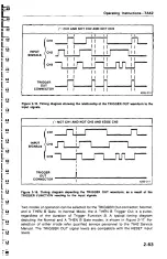
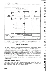
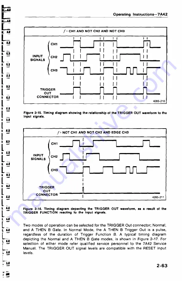
Figure
2-15. Timing
diagram showing
the
relationship
of the TRIGGER OUT waveform to the
Input
signals.
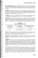
Figure
2-16. Timing diagram
depectlng the TRIGGER OUT waveform,
as a result of the
TRIGGER
FUNCTION
reacting to the input signals.
Two
modes
of
operation
can
be
selected
for
the
TRIGGER
Out
connector;
Normal,
and A THEN
B
Gate. In
Normal
Mode,
the
A
THEN
B Trigger
Out
is
a
pulse,
regardless
of
the
duration
of
Trigger
Function
B.
A
typical
timing
diagram
depicting
the
Normal
and
A
THEN
B
Gate
modes,
is
shown
in
Figure
2-17. For
selection
of
either mode
refer
qualified
service
personnel
to
the 7A42
Service
Manual.
The
TRIGGER
OUT
signal
levels
are
compatible
with
the
RESET input
levels.
2-63


