APPLICATIONS
In
this
section
we
give
some
examples of
how
your 7A42
Logic
Triggered Vertical
Amplifier
can
be
used
in
specific
applications. These
applications
provide
sufficient
detail
for
you
to
adapt
them
to
other
related
applications.
Contact
your
Tektronix Field
Office
or
representative
for
assistance in making
measurements
that
are
not
described
in
this manual.
APPLICATION
1
DISPLAYING
FOUR CHANNELS OF DATA
WITH THE 7A42
High-speed
delay
comparisons
and
timing
measurements
on
data
lines
are
often
difficult
to
accomplish
with
a
high
degree
of
accuracy.
However,
with
less
than
200
picoseconds
time
delay
between
any of
the
four
input
channels,
the
7A42
makes
these measurements with
ease
and
confidence.
For
example,
the
combinational triggering
functions
provided
on the 7A42 front
panel
make
it
a
simple matter
to
look
at
any
count
of
a
four-bit
counter.
A
master
clock
signal
can
be
connected
to
the 7A42
EXT
CLOCK
INPUT
and
displayed
on
the
Trigger View
trace.
MEASUREMENT
TECHNIQUE
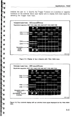
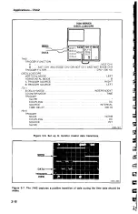
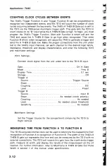
Figure
3-1 illustrates
an
example
of
viewing
the
output
of
a
counter
when
the
countdown
reaches
a
value
of
decimal
“10,
”
where
the
LSB
is
displayed
on
the
CH1
trace
and
the
MSB
is
displayed
on
the
CH4
trace.
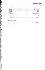
To
accomplish
this,
enter
the
7A42
Trigger
Function:
NOT
CH1
AND
CH2
AND
NOT
CH3
AND
CH4.
The
7A42 can
store and
recall
two
independent
trigger
functions;
function
“A
”
and
function
“
B."
To
enter these
two trigger
functions
press
the
A
pushbutton,
enter
the
first
Boolean trigger function equation, push
the
B
pushbutton
and
enter
the
second
Boolean
trigger function
equation.
Either
function
may
be
recalled
by
merely
selecting
Trigger
Function
A or
Trigger Function
B.
When
the
input
signals
satisfy
the
programmed
logic
function,
the
7A42 will
generate
a
trigger.
The
trigger
can
be
routed
externally
to other measurement
devices
and/or
internally
through
the
7000-series
mainframe
trigger
path
to
a
time
base
or special-purpose
plug-in
unit,
in
either horizontal
compartment.
No
external
connection
to
the
time
base
is
necessary
to
provide
a
triggered
display
on
the
oscilloscope
crt.
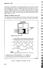
The
Trigger
View
trace
enables
you
to
see the
state
of the
programmed
trigger
function
in
addition to the
selected
channel
displays;
see
Figure
3-2.
The
Trigger
3-1


