Applications
—
7A42
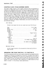
COUNTING
CLOCK CYCLES
BETWEEN
EVENTS
The
7A42's
Trigger
Function
A
and
Trigger
Function
B can
be
programmed
to
recognize
two
independent
events,
and
the
7D15
will
count
the
number
of
clock
cycles
occurring between
the
two
events.
The
7A42's
A
THEN
B
Gate
out is
sent
to
the
7D15
via
the
7000-series
mainframe
trigger
path.
This
gate
tells
the
7D15
to
count
clocks
on
its
“
B”
input
while
the
A
THEN
B Gate
is
high.
To
begin,
you
must
program
the
7A42's
Trigger
Function.
Start
with
Function
A
which
will
arm
the
7A42
and
cause the
A
THEN
B
Gate
to
go
high
when
recognized.
Then
enter
Function
B
which,
when
recognized,
will
cause
the
7A42
to
generate
a
trigger
and
send
the
A
THEN
B
Gate
low.
Make
the
proper
connections
from
the
unit
under
test
to
the
7A42's
input
channels,
set
each
channel
for
the
desired logic
family,
impedance,
threshold,
and
display
characteristics,
and
enter
the
following
7D15
and
mainframe
settings:
7D15
Settings:
Connect
clock
signal
from
the
unit under
test
to
the
7D15
B input.
Gate......................................................................................... CH A
Gate
Mode............................................................................................. Freq
B
Display
Time.................................................................................
0.1
sec
Storage...................................................................................................
Off
Trigger
A
Source.........................................................................
Trigger
Source
Slope
.....................................................................................................
+
Coupling............................................................................................DC
Level
..............................................................................................
Preset
Trigger
B
Source.....................................................................................
Input
B
Slope
....................................................
As needed
(clock
polarity)
Coupling............................................................................
As
needed
Level
.....................................................
As
needed (clock
threshold)
Sensitivity
..........................................................................
As
needed
Mainframe
Settings:
Set
the Trigger
Source
for
the
compartment
containing
the
7D15
to
Right
Vertical.
MEASURING
TIME FROM FUNCTION
A TO FUNCTION B
The
7D15's
accurate
internal
clock can
be
used
to
determine
the
elapsed
time
from
recognition
of
Function
A
to
recognition
of Function
B.
The
width
of
the
7A42's
A
THEN
B gate
out
represents
this
time
and
can
be
measured
by
the
7D15
with
no
external
connections.
The
7D15
will
receive
this
gate from
the
mainframe's
trigger
path,
measure
its
width,
and
display
the
results
of
the
measurement
on
the
CRT
readout.
For
further
information,
refer
to
Mainframe
A
THEN
B Gate
Out
Pulse
Width
in
section
1
of
this
manual
under
specifications.
3-12

