Operating Instructions
—7A42
®
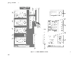
TRIGGER
FILTER—
Variable
control
sets minimum duration
of
TRIGGER
FUNCTION
output
before
it
is
sent
to
the
time
base or
TRIGGER
OUTput
connector.
TRIGGER
OUT—
Provides
a
front-panel
output
of
the
trigger
signal.
®
EXT
CLOCK INPUT—
Provides
external
clock
input
for
synchronizing
triggers
to
an
external
clock
signal
source
(EXT
CLOCK
SYNC
light
must
be
on).
EXT CLOCK
SYNC—
Pushbutton
switch
allows
an
external
clock
to
qualify
the
TRIGGER
FUNCTION.
Pushbutton
switch
selects
positive
going
or
negative
going
edge
of
the
external
clock
signal
which
qualifies
TRIGGER
FUNCTION.
®
A,
B, A THEN B—
Two
independent
TRIGGER
FUNCTION
programs
are
available
(A
and
B).
The
A
THEN B
is
a nested
combination
where
A
must
occur
to arm
triggering before B
is
allowed
to
produce
a
trigger
output.
RESET
—
External
input
to disable
the
TRIGGER
FUNCTION
output
and
disarm
the
A
THEN
B
nested
triggering;
no
arming
or triggering
can occur
while
a
high
level
is
applied.
TRIGGER
FUNCTION—
LED
display
indicates
the
Boolean
function
which
will
produce
a
TRIGGER
FUNCTION
output.
Number
6,
7,
and
10
controls
are
used to
program
TRIGGER
FUNCTION
lights
SWITCHING
THRESHOLD
VOLTS—
LED
display indicates
threshold
voltage
of the
channel selected
by
controls
listed under
number
6 or
displays
probe
offset
LEVEL—
Two
pushbutton
switches
set
threshold
voltage
of
channel
selected
by
the
controls
listed
under
number 6
PROBE
OFFSET—
Measures
offset
voltage
of
probe
connected
to
the
channel
selected
by controls
listed
under
number
1
PROG
CHAN/TRIG
must be set to CHAN.
2PROG
CHAN/TRIG must be set to TRIG.
3PROG
CHAN/TRIG must be set to CHAN, and THRESH must be active.
2-12


