Operating
Instructions—7A42
The
SWITCHING
THRESHOLD
VOLTS indicator
and
mainframe
crt
readout
display
indicate a
self-test
failure
with
a
numeric
code.
All
of
the
self-test
code
numbers
are
listed
in
Table
2-1,
along
with
the
nature
of
the
failure
and
an
explanation
of
the severity of the
failure.
The
severity
information
is
helpful
in
determining
if
the
7A42
can
still
be
used
for
the
intended
purpose
or
whether
repair
is
necessary.
To
continue
the
self-test
sequence,
press
any
of
the
7A42
front-panel
pushbuttons.
NOTE
There
should
be no
connections to the RESET EXT CLOCK, and TIP Inputs
during
the
time Self Test is running.
NOTE
Before
the
7A42
Self Test
feature can
verify that the 7A42 readout circuitry is
operating
properly,
mainframe crt readout system must be set to the "Freerun”
(non-Gated)
mode.
DISPLAY
MEDIA
TYPICAL DISPLAY
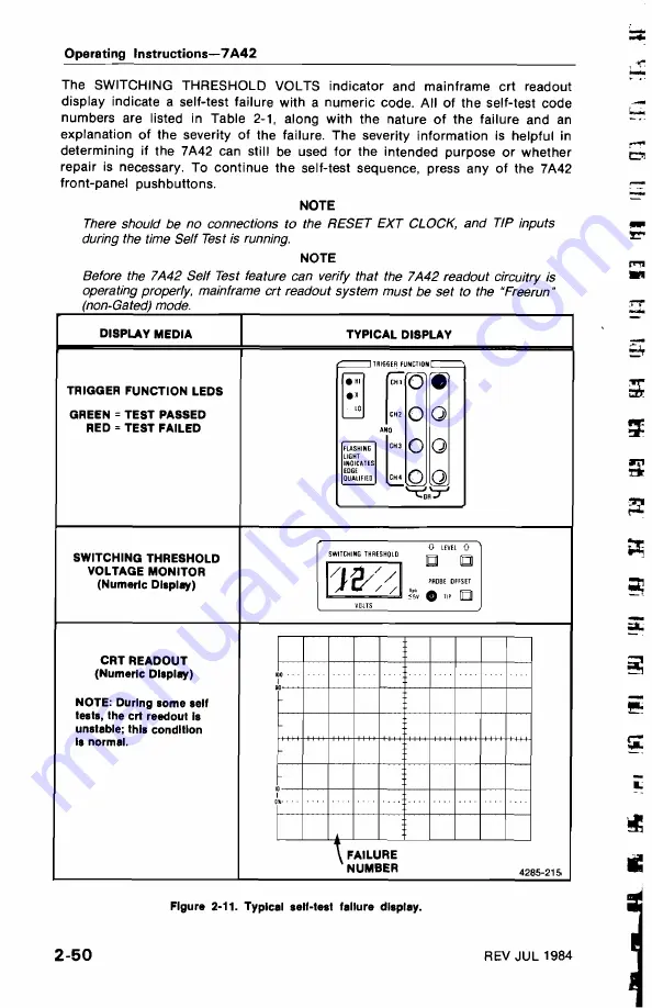
TRIGGER FUNCTION
LEDS
GREEN
=
TEST PASSED
RED =
TEST
FAILED
SWITCHING
THRESHOLD
VOLTAGE
MONITOR
(Numeric Display)
CRT
READOUT
(Numeric Display)
NOTE: During
some
self
tests,
the
crt reedout Is
unstable; this condition
Is normal.
Figure 2-11.
Typical self-test
failure display.
2-50
REV
JUL
1984


