Applications—7A42
APPLICATION 4
DETECTING AND DISPLAYING
BUS
CONTENTION
In
bus-oriented systems,
one
problem
which
is
difficult
to
detect
with
either
an
oscilloscope
or
a
logic
analyzer
is
that
of
bus
contention.
Bus
contention
arises
when
more
than
one
component
attempts
to
drive
a common
bus
at
the
same
time.
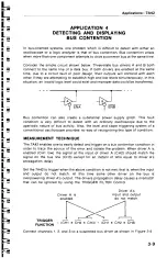
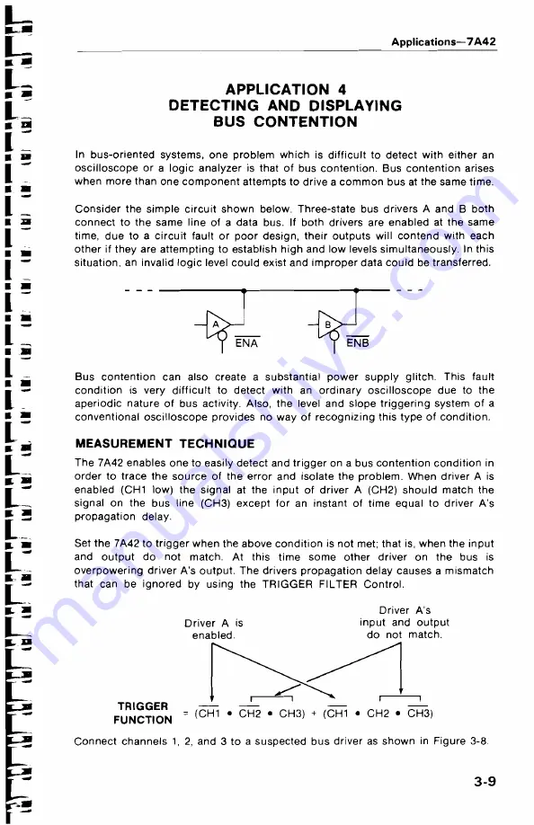
Consider
the
simple
circuit
shown
below.
Three-state
bus
drivers
A
and
B
both
connect
to the
same
line
of a data
bus. If
both
drivers
are
enabled
at
the
same
time, due
to a
circuit
fault
or
poor
design,
their outputs
will
contend
with each
other
if
they
are
attempting
to
establish
high
and low
levels
simultaneously.
In
this
situation,
an
invalid
logic
level
could
exist
and
improper
data
could
be
transferred.
Bus
contention
can
also
create
a substantial
power
supply
glitch.
This
fault
condition
is
very
difficult
to
detect
with
an
ordinary
oscilloscope
due
to
the
aperiodic
nature
of
bus
activity.
Also,
the level
and
slope triggering
system
of
a
conventional
oscilloscope
provides
no
way
of
recognizing
this
type
of
condition.
MEASUREMENT TECHNIQUE
The
7A42
enables
one
to
easily
detect
and
trigger
on
a bus
contention condition
in
order
to
trace
the
source
of
the
error
and isolate
the
problem.
When driver A
is
enabled
(CH1
low)
the
signal
at
the
input
of
driver
A
(CH2)
should
match
the
signal
on
the
bus
line
(CH3)
except
for
an
instant
of
time equal to
driver
A’
s
propagation
delay.
Set
the
7A42
to
trigger
when
the
above
condition
is
not
met;
that
is,
when
the
input
and
output
do not
match.
At
this
time
some other
driver
on
the
bus
is
overpowering
driver
A
’
s output. The
drivers
propagation
delay
causes
a
mismatch
that
can
be
ignored
by
using
the
TRIGGER
FILTER Control.
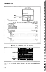
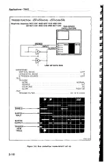
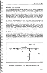
Connect
channels
1,
2,
and
3
to a
suspected
bus
driver
as
shown
in
Figure
3-8.

