7B53A/7B53AN
OPTION 5
CALIBRATION
PROCEDURE
Optional
Test Equipment
067-0601-00
Calibration Fixture (Television Test Signal
Generator)
Plug-In
Cards for
067-0601-00 Generator
067-5001-00
System A
405/50
067-5002-00
System M
525/60
067-5003-00
System
B
625/50
067-5004-00
System E
819/50
067-5005-00
System
F
819/50
067-5006-00
EIA Standard
729/60
067-5007-00
EIA Standard
875/60
067-5008-00
EIA Standard
945/60
067-5009-00
EIA Standard
1029/60
067-5010-00
EIA Standard
1201/60
CHECK/ADJUST
PROCEDURE
1.
Check
TP900
Waveform
a.
Connect
a composite video
signal to the vertical
plug-in unit.
b. Set
the 7B53A/7B53AN
OPTION 5
controls
as
follows:
Main
Triggering
Amplifier
SLOPE
MODE
COUPLING
SOURCE
MAIN TIME
BASE
AUTO
DC
TV FIELD
NOTE
If
the trigger
pick-off circuit is overdriven or the
piug-in
Vertical Position control is rotated to its fully
clockwise
or counterclockwise position,
the wave
form
may become
distorted. If so, the sync separator
will
not
function
properly unless the display ampli
tude is 2 major
divisions as described in part c of this
step
and
the Vertical Position control is moved away
from
its extreme
position.
2.
Check
TP926 Waveform
and Adjust R914
a.
Connect
the
10X probe to
TP926. Set the
test
oscilloscope controls to
obtain
a stable display.
b. Adjust the Clipping
Level control R914
by rotating
the
control fully clockwise. Then, rotate the control
counterclockwise
until
one or more
negative-going pulses in
a
group are displayed
on the
test oscilloscope during the
vertical
sync pulse interval. The
exact number of pulses is
dependent on
the
television standard of
the composite
video
signal being
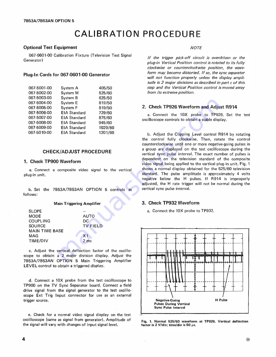
applied to the vertical plug-in unit. Fig. 1
shows a normal
display obtained for the 525/60 television
standard.
The pulse amplitude
is approximately
4 volts
negative
below the H pulses. If R914 is improperly
adjusted, the
H rate trigger
will not be normal during the
vertical sync
pulse interval.
3.
Check
TP932
Waveform
a.
Connect the 10X probe to TP932.
MAG
X1
TIME/DIV
2 ms
c. Adjust
the
vertical deflection factor of the oscillo
scope
to obtain a
2 major division display. Adjust the
7B53A/7B53AN
OPTION 5 Main Triggering
Amplifier
LEVEL
control to obtain
a triggered display.
d. Connect a
10X
probe from the test oscilloscope to
TP900
on
the TV
Sync Separator board. Connect a field
drive
signal from the signal
generator to the test oscillo
scope Ext
Trig Input connector for use as an external
trigger source.
e.
Check
for a
normal video signal display on the test
oscilloscope
(same as signal from
generator).
Amplitude of
the signal will vary
with changes
of input signal
level.
Fig.
1. Normal 525/60 waveform at TP926. Vertical deflection
factor
is
2 V/div;
time/div is 50 µs.
4
Summary of Contents for 7B53A
Page 10: ......
Page 11: ...7B53A 7B53AN OPTION 5 TV partial SYNC SEPARATOR TRIGGER PREAMP...


