Section 2--DM 501 A
OPERATING INSTRUCTIONS
Installation and Removal l nslrucllons
The DM S01A is calibrated and ready to use when
received. It operates in one compartment of a TM SOO
Series power module. Refer tothe power module instruc
tion manual for line voltage requirements and power
module operation.
�
Turn the power module off before inserting or
removing the
OM
SOIA; otherwise, arcing may occur
at the rear interface connectors. Arcing reduces the
connectors useful life and damage may be done to
the plug-in circuitry.
POWER
MODULE
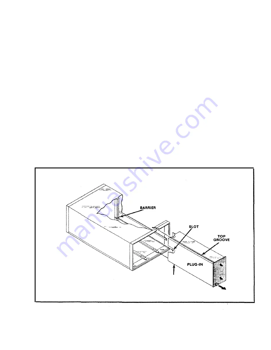
Check to see that the plastic barriers on the inter
connecting jack of the selected power module compart
ment match the cut-outs i n the OM S01A circuit board
edge connector. If they don't match, do not insert the plug
in until proper identification is made. When the units are
properly matched, align the OM S01A chassis with the
upper and lower guides (see Fig. 2-1 ) of the selected
compartment. I nsert the OM 501 A into the compartment
and press firmly to seat the circuit board in the i nter�
connecting jack. The LEO display should be visible when
the power module power switch i s turned on.
To remove the OM S01A, pull the release l atch (located
on the lower left corner) until the i nterconnecting jack
disengages. The OM S01 A will now slide out.
BOTTOM
GROOVE
2749-2
Fig_
2-1. Installation and removal.
REV
A AUG 1980
English
2·1
Summary of Contents for DM501A
Page 1: ......
Page 2: ......
Page 6: ...OM 501A OM SOiA Oigita Multlmeter xiv AUG 1980...
Page 13: ......
Page 18: ...Verso Filler Page z z...
Page 21: ...Operating Instructions OM SOlA FIg 2 2 Controls and connectors REV A AUG 1980 English 2 3...
Page 24: ...Verso Filler Page z z...
Page 25: ...OM 501A Japanese 2 3...
Page 26: ...Verso Filler Page z z...
Page 48: ...Verso Filler Page z z...


