Calibration Procedure-OM SOiA
Performance Check Procedure
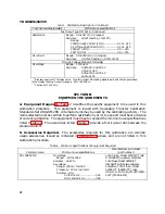
6. Check Ohms Accuracy
a. Connect a resistance standard to the VOL TSIn and
lOW connectors.
b. Press the kQ function push button and the ap
propriate H I or LO push button as indicated i n Table 4-6.
c. Press the range push bulton and set the resistance
standard as listed in Table 4-6.
d. Check-that the DM S01A display reads within the
display limits for the ambient temperature as l isted i n
Table 4-6.
e. Remove all connections.
7.
C heck Dc Current Accuracy
a. Connect the dc current source to the rnA and LOW
connectors through appropriate cables and connectors
with the positive source to the mA connector.
b. Press the mA DC function push button.
c. Press the range push button and set the current
source as listed in Table 4-7.
d. Check-that the DM S01A display readout is within
the display limits for the ambient temperature as shown in
Table 4-7.
e. Remove the de current source and all connections.
8.
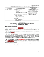
Check Ac Current Accuracy
a. Connect the precision ac current souce to the rnA
and LOW connectors through appropriate cables and
connectors.
b. Press the mA AC function push button.
Co
Press the range push button and set the current
source as listed in Table 4-8.
d. Check-that the DM S01A display reads within the
display limits for the ambient temperature as li sted i n
Table 4-8.
4-4
e. Remove the AC current source and all connections.
9.
Check Temperature Accuracy
a. Connect the temperature probe to the TEMP con
nector located on the front panel.
b. Press the TEMpo C push button.
c. Set the temperature bath for the first temperatures
shown i n the Temperature column i n Table 4�9.
d. I nsert the probe i n the bath and allow the probe to
stabilize at the selected temperature.
e. Check-that the display limits are as listed i n Table
4-9.
f. Repeat parts c, d, and e for the subsequent
temperatures l isted i n Table 4-9.
g. This completes the front panel performance check.
Rear Interface Accuracy Checks
To verify the accuracy of the dc voltage, ac voltage and
resistance modes via the O M 501 A rear interface, follow
the steps outlined in the Performance Check Procedure
forthe front panel i nput connectors, but apply the voltages
and resistances t o rear interface pins 288 (HI) and 28A
(LO). Access to the rear i nterface pins is most easily made
using a TM SOo-series, Option 2 power module.
Press the front panel EXT -INT push button to select
rear interface i nput and use Table 4-10, Table 4-1 1 , Table
4-12. Table 4-13, or Table 4-1 4 for the appropriate input
voltages, frequencies, and display l imits.
NOTE
The output cable fixture from the calibrating sources
to the rear i
nt
e
r
fac
e
pins
may have to be modified to
accommodate accuracy checks via the rear inter
face.
@
Summary of Contents for DM501A
Page 1: ......
Page 2: ......
Page 6: ...OM 501A OM SOiA Oigita Multlmeter xiv AUG 1980...
Page 13: ......
Page 18: ...Verso Filler Page z z...
Page 21: ...Operating Instructions OM SOlA FIg 2 2 Controls and connectors REV A AUG 1980 English 2 3...
Page 24: ...Verso Filler Page z z...
Page 25: ...OM 501A Japanese 2 3...
Page 26: ...Verso Filler Page z z...
Page 48: ...Verso Filler Page z z...


