TB 9-6625-1957-35
6
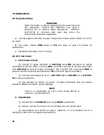
7. Equipment Setup
WARNING
HIGH VOLTAGE is used or exposed during the performance of
this calibration. DEATH ON CONTACT may result if
personnel fail to observe safety precautions. REDUCE
OUTPUT(S) to minimum after each step within the
performance check where applicable.
a
. Remove TI protective cover from TI only to make adjustments and replace upon
completion.
b.
Connect T1 to power module using an extender. Connect power module to a 115 V
ac source. Pull power module
PWR
switch to
ON
and allow at least 30 minutes for
stabilization.
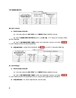
8. Dc Voltage
a. Performance Check
(1) Set
RANGE/FUNCTION
switch to
2 DC VOLTS
and set
INPUT INT
to
OUT:
EXT
(out).
(2) Short
INPUT HI
and
LO
terminals. If TI does not indicate .0000, perform
b
below.
(3) Remove short and connect calibrator
OUTPUT
terminals to TI
INPUT HI
and
LO
terminals.
(4) Set TI
RANGE/FUNCTION
switch and set calibrator output as specified in
table 3. If TI does not indicate within the specified limits, perform corresponding
adjustment procedure.
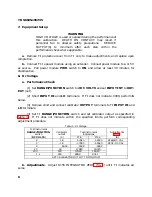
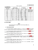
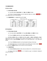
Table 3. Dc Voltage
Test instrument
RANGE/FUNCTION
switch
Calibrator
output
Test instrument
indications
Adjustments
(
DC VOLTS
)
(V)
Min
Max
(R)
2
1.8
1.7980
1.8020
R182+DC CAL
2
-1.8
-1.7980
-1.8020
R202 - DC CAL
2
.5555
.5548
.5562
20
18
17.980
18.020
200
180
179.80
180.20
1 k
900
898.9
901.1
SET CALIBRATOR OUTPUT TO MINIMUM
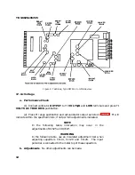
b. Adjustments
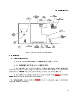
. Adjust R155 INTEGRATOR ZERO (fig. 1) until TI indicates all
zeros.
Summary of Contents for DM501A
Page 1: ......
Page 2: ......
Page 6: ...OM 501A OM SOiA Oigita Multlmeter xiv AUG 1980...
Page 13: ......
Page 18: ...Verso Filler Page z z...
Page 21: ...Operating Instructions OM SOlA FIg 2 2 Controls and connectors REV A AUG 1980 English 2 3...
Page 24: ...Verso Filler Page z z...
Page 25: ...OM 501A Japanese 2 3...
Page 26: ...Verso Filler Page z z...
Page 48: ...Verso Filler Page z z...


