TB 9-6625-1957-35
8
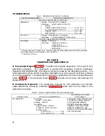
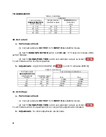
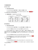
Table 4. Resistance
Calibrator
Test instrument
RANGE/FUNCTION
switch settings
Output nominal
resistance values
ERROR
display
indications
±
(%)
2
k
Ω
1.9
k
Ω
.31
20
k
Ω
19
k
Ω
.31
2
M
Ω
1.9
M
Ω
.31
20
M
Ω
19
M
Ω
.51
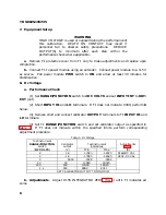
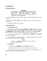
10. Dc Current
a. Performance Check
(1) Connect calibrator
OUTPUT
to TI
INPUT HI
and
LO
terminals.
(2) Set TI
RANGE/FUNCTION
switch to
2 DC mA
. If TI does not indicate .0000,
perform
b
below.
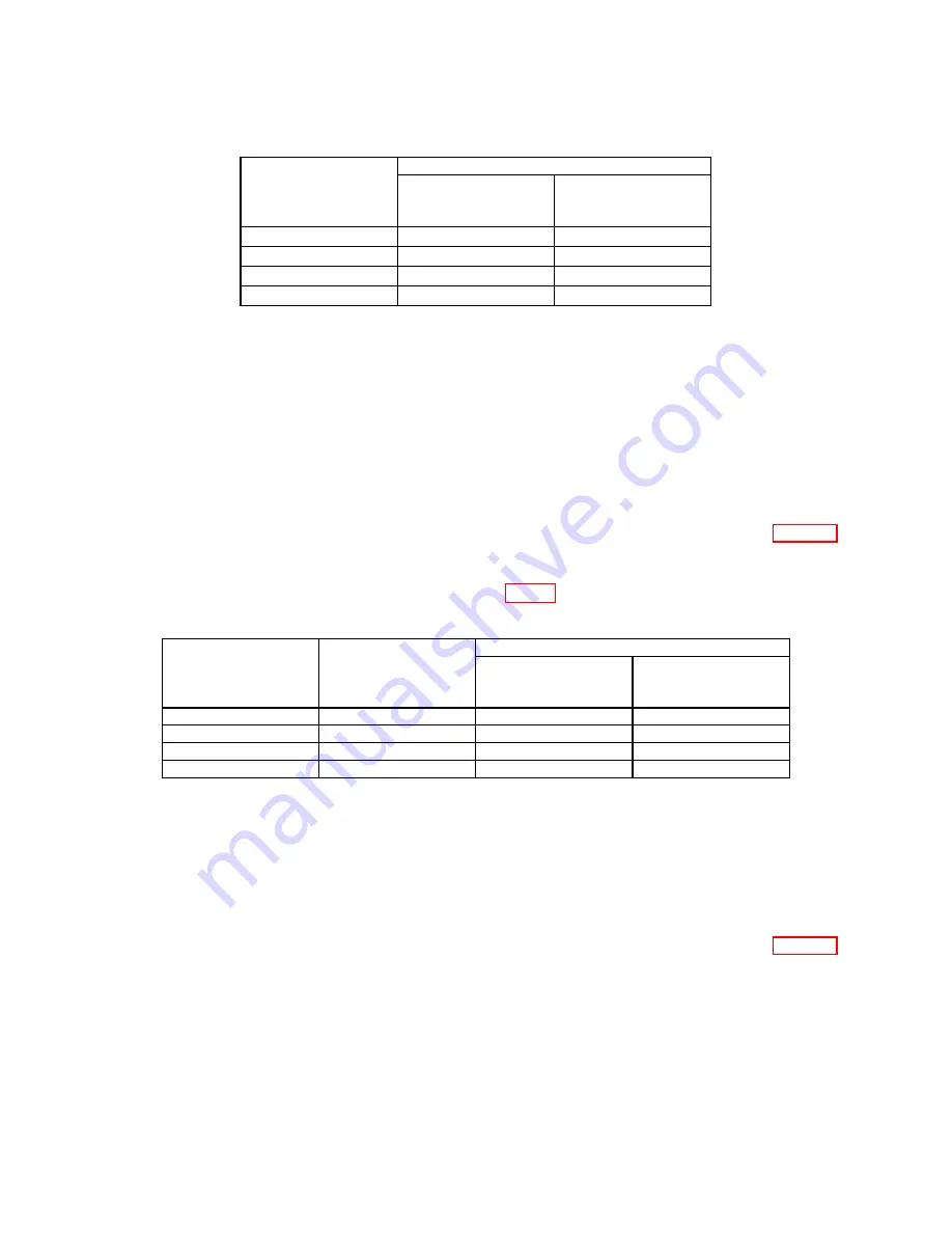
(3) Set TI
RANGE/FUNCTION
switch and calibrator output as listed in table 5.
TI will indicate within the limits specified.
b. Adjustments
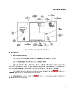
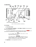
. Adjut R50 CURRENT ZERO (fig. 1) until TI indicates .0000 (R).
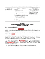
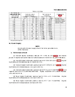
Table 5.
Dc Current
Test instrument
Test instrument indications
RANGE/FUNCTION
switch settings
(Dc mA)
Calibrator output
(dc current)
Min
Max
2
1.8
mA
1.7954
1.8046
20
18
mA
17.954
18.046
200
180
mA
179.54
180.46
2000
1.8
A
1795.4
1804.6
11. Ac Voltage
a. Performance Check
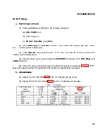
(1) Connect calibrator
OUTPUT
to TI
INPUT HI
and
LO
terminals.
(2) Set TI
RANGE/FUNCTION
switch and calibrator output as listed in table 6.
TI will indicate within the specified limits; if not, perform adjustments indicated.
b. Adjustments
. No other adjustments can be made.
Summary of Contents for DM501A
Page 1: ......
Page 2: ......
Page 6: ...OM 501A OM SOiA Oigita Multlmeter xiv AUG 1980...
Page 13: ......
Page 18: ...Verso Filler Page z z...
Page 21: ...Operating Instructions OM SOlA FIg 2 2 Controls and connectors REV A AUG 1980 English 2 3...
Page 24: ...Verso Filler Page z z...
Page 25: ...OM 501A Japanese 2 3...
Page 26: ...Verso Filler Page z z...
Page 48: ...Verso Filler Page z z...


