TB 9-6625-1957-35
9
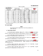
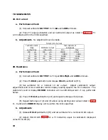
Table 6. Ac Voltage
Test instrument
RANGE/FUNCTION
switch settings
Calibrator output
voltage frequency
Test instrument
indications
Adjustments
(
AC VOLTS
)
Voltage
Frequency
Min
Max
(R)
2
1.8 V
1.0
kHz
1.7872
1.8128
R70 AC CAL
20
18
V
8.0
kHz
17.872
18.128
C42 20 V AC COMP
200
180
V
8.0
kHz
178.72
181.28
C45 200 V AC COMP
500
450
V
1
8.0
kHz
446.65
453.35
C48 500 V COMP
500
450
V
1
20
kHz
444.58
455.42
- - -
500
450
V
1
20
Hz
444.58
455.42
- - -
500
450
V
1.0
kHz
446.65
453.35
- - -
200
180
V
20
Hz
177.82
182.18
- - -
200
180
V
1.0
kHz
178.72
181.28
- - -
200
180
V
20
kHz
177.82
182.18
- - -
20
18
V
20
Hz
17.782
18.218
- - -
20
18
V
1.0
kHz
17.872
18.128
- - -
20
18
V
20
kHz
17.782
18.218
- - -
2
1.8 V
20
Hz
1.7782
1.8218
- - -
2
1.8 V
1.0
kHz
1.7872
1.8128
- - -
2
1.8 V
20
kHz
1.7782
1.8218
- - -
1
Power amplifier required.
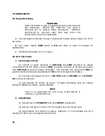
12. Power Supply
NOTE
Do not perform power supply check if all other parameters are
within tolerance.
a. Performance Check
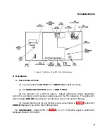
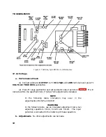
(1) Connect digital multimeter between TP 1 PIN 24 +5V (fig. 1) and chassis
ground. If digital multimeter does not indicate between 4.9 and 5.1 V dc, perform
b
below.
(2) Connect digital multimeter positive lead to TP 2 VR 410 +12 V (fig. 1). Digital
multimeter will indicate between 11.0 and 13.0. V dc.
(3) Connect digital multimeter positive lead to TP 3 PIN 15 -12 V (fig. 1). Digital
multimeter will indicate between -11.4 and -12.6 V dc.
(4) Connect digital multimeter positive lead to TP 6 +12 V FLOATING (fig. 1) and
negative lead to TP 5 FLOATING GROUND. Digital multimeter will indicate between
+11.4 and +12.6 V dc.
(5) Move digital multimeter positive lead to TP4 -12 V FLOATING. Digital
multimeter will indicate between -11.4 and -12.6 V dc.
(6) Move digital multimeter positive lead to TP 7 +5 V FLOATING. Digital
multimeter will indicate between
+
4.5
and +5.5 V dc.
Summary of Contents for DM501A
Page 1: ......
Page 2: ......
Page 6: ...OM 501A OM SOiA Oigita Multlmeter xiv AUG 1980...
Page 13: ......
Page 18: ...Verso Filler Page z z...
Page 21: ...Operating Instructions OM SOlA FIg 2 2 Controls and connectors REV A AUG 1980 English 2 3...
Page 24: ...Verso Filler Page z z...
Page 25: ...OM 501A Japanese 2 3...
Page 26: ...Verso Filler Page z z...
Page 48: ...Verso Filler Page z z...


