TB 9-6625-1957-35
11
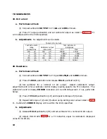
16. Dc Voltage
a. Performance Check
(1) Press pushbuttons as listed in (a) through (c) below:
(a)
VOLTS DC
(in).
(b)
2 V
range (in).
(c)
INPUT EXT/INT
(out) (
EXT
).
(2) Short
VOLTS/
Ω
Ω
and
LOW
terminals. If TI does not indicate between -.0002
and
+.0002, perform
b
(l) below.
(3) Press
200 mV
range pushbutton. If TI does not indicate between -00.02 and
+00.02, perform
b
(2) below.
(4) Remove short and connect calibrator
OUTPUT
terminals to TI
VOLTS/
Ω
Ω
and
LOW
terminals.
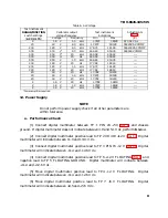
(5) Press TI range pushbutton and set calibrator output as specified in table 7. If TI
does not indicate within the specified limits, perform adjustments indicated.
b. Adjustments
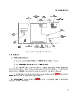
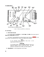
(1) Adjust 2 V DC 0 R1405 (fig. 2) until TI indicates all zeros (R).
(2) Adjust 200 mV DC 0 R1415 (fig. 2) until TI indicates all zeros (R).
Table 7. Dc Voltage
Test instrument
range
Calibrator
output
Test instrument
indications
Adjustments
pushbuttons
(V dc)
Min
Max
(R)
2 V
1.9
1.8989
1.9011
2VDC
R1505
2 V
-1.9
-1.8989
-1.9011
- - -
200mV
.190
189.88
190.12
200 mV DC R1504
20V
19
18.989
19.011
20 VDC
R1104
200V
190
189.89
190.11
200 VDC
R1110
1000 V dc
1000
999.3
1000.7
1000VDC
R1114
SET CALIBRATOR OUTPUT TO MINIMUM
Summary of Contents for DM501A
Page 1: ......
Page 2: ......
Page 6: ...OM 501A OM SOiA Oigita Multlmeter xiv AUG 1980...
Page 13: ......
Page 18: ...Verso Filler Page z z...
Page 21: ...Operating Instructions OM SOlA FIg 2 2 Controls and connectors REV A AUG 1980 English 2 3...
Page 24: ...Verso Filler Page z z...
Page 25: ...OM 501A Japanese 2 3...
Page 26: ...Verso Filler Page z z...
Page 48: ...Verso Filler Page z z...


