background image

Pinpoint triggers

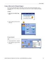
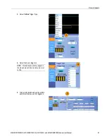
Using a (Main) and b (Delayed) triggers

You can use the A Event (Main) trigger for simple signals or combine it with the B Event (Delayed) trigger to capture
more complex signals. After the A Event occurs, the trigger system looks for the B Event before triggering and displaying
the waveform.

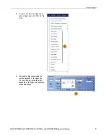
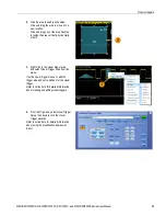
A trigger

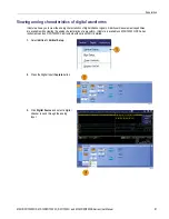
1.

Select

Trig > A Event (Main) Trigger

Setup...

.

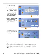
2.

Set the A trigger type and source in the
A Event tab.

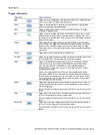
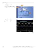
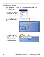
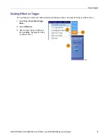
B trigger (Delayed)

NOTE.

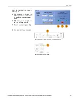
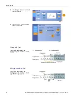
3.

Choose a function in the A

B Seq tab.

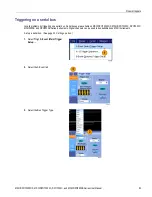
4.

Set the trigger delay time or the number
of B events.

MSO/DPO70000DX, MSO/DPO70000C, DPO7000C, and MSO/DPO5000B Series User Manual

75

Summary of Contents for DPO5000/B

Page 1: ...X Series Mixed Signal Oscilloscopes DPO70000C DX Series Digital Phosphor Oscilloscopes DPO7000C Series Digital Phosphor Oscilloscopes MSO5000B and DPO5000B Series Oscilloscopes ZZZ User Manual P071298004 071 2980 04 ...

Page 2: ......

Page 3: ...oscopes DPO70000C DX Series Digital Phosphor Oscilloscopes DPO7000C Series Digital Phosphor Oscilloscopes MSO5000B and DPO5000B Series Oscilloscopes ZZZ User Manual xx This document supports firmware version 6 8 www tektronix com 071 2980 04 ...

Page 4: ...privileges reserved TEKTRONIX and TEK are registered trademarks of Tektronix Inc TekScope TekConnect Wave Inspector and TekLink are registered trademarks of Tektronix Inc FastFrame OpenChoice iCapture MyScope MultiView Zoom SignalVu TekExpress TriMode TekSecure TekProbe TekVPI TekVISA MagniVu DPX and PinPoint are trademarks of Tektronix Inc Contacting Tektronix Tektronix Inc 14150 SW Karl Braun Dr...

Page 5: ...s taxes and any other charges for products returned to any other locations This warranty shall not apply to any defect failure or damage caused by improper use or improper or inadequate maintenance and care Tektronix shall not be obligated to furnish service under this warranty a to repair damage resulting from attempts by personnel other than Tektronix representatives to install repair or service...

Page 6: ......

Page 7: ...emoving the power 10 Securing the oscilloscope 11 Connecting to a network 11 Adding a second monitor 12 Operating system restore 15 Installing the MSO5000B and DPO5000B hard drive 16 Getting acquainted with your instrument 17 Front panel 17 Side and rear panels 20 Interface and display 23 Control panel 25 Accessing online help 28 Accessing menus and control windows 29 Inspect your instrument 30 Ve...

Page 8: ...sing a Main and b Delayed triggers 75 Triggering with B Event Scan 78 Triggering on a parallel bus 80 Triggering on a serial bus 83 Triggering using Visual Triggers Visual Triggering 84 Setting up Action on Event 86 Sending E Mail on Trigger 87 Setting up E Mail on Event 88 Using horizontal delay 90 Display a waveform 91 Setting the Display Style 91 Setting the Display Persistence 92 Setting the D...

Page 9: ...Recalling waveforms 155 Saving digital waveforms 156 Saving instrument setups 157 Recalling instrument setups 158 Saving measurements 159 Saving user masks 160 Saving histogram data 161 Saving timestamps 162 Copying your results to the clipboard 163 Printing a hard copy 165 Run application software 166 Application examples 168 Capturing intermittent anomalies 168 Using the extended desktop and Ope...

Page 10: ... 187 P6616 General Purpose Logic Probe instructions 187 Product description 187 Connecting the probe to the oscilloscope 188 Connecting the probe to your circuit 189 Functional check 189 Typical application 190 Accessories 190 Specifications 191 Safety summary 192 Safety terms and symbols in this manual 192 Contacting Tektronix 193 Warranty information 193 Index iv MSO DPO70000DX MSO DPO70000C DPO...

Page 11: ...uctors are exposed While using this product you may need to access other parts of a larger system Read the safety sections of the other component manuals for warnings and cautions related to operating the system When incorporating this equipment into a system the safety of that system is the responsibility of the assembler of the system To avoid fire or personal injury Use proper power cord Use on...

Page 12: ...n it off and disconnect the power cord Clearly mark the product to prevent its further operation Before use inspect voltage probes test leads and accessories for mechanical damage and replace when damaged Do not use probes or test leads if they are damaged if there is exposed metal or if a wear indicator shows Examine the exterior of the product before you use it Look for cracks or missing pieces ...

Page 13: ...orming any service procedures To avoid electric shock Do not touch exposed connections Do not service alone Do not perform internal service or adjustments of this product unless another person capable of rendering first aid and resuscitation is present Disconnect power To avoid electric shock switch off the product power and disconnect the power cord from the mains power before removing any covers...

Page 14: ...indicates an injury hazard immediately accessible as you read the marking WARNING indicates an injury hazard not immediately accessible as you read the marking CAUTION indicates a hazard to property including the product When this symbol is marked on the product be sure to consult the manual to find out the nature of the potential hazards and any actions which have to be taken to avoid them This s...

Page 15: ...a Western Road Bracknell RG12 1RF United Kingdom 1 This product is intended for use in nonresidential areas only Use in residential areas may cause electromagnetic interference 2 Emissions which exceed the levels required by this standard may occur when this equipment is connected to a test object 3 If interconnect cables are used they must be low EMI shielded cables such as the following Tektroni...

Page 16: ...ecognized testing laboratory listing UL 61010 1 Safety Requirements for Electrical Equipment for Measurement Control and Laboratory Use Part 1 General Requirements UL 61010 2 030 Safety Requirements for Electrical Equipment for Measurement Control and Laboratory Use Part 2 030 Particular requirements for testing and measuring circuits Canadian certification CAN CSA C22 2 No 61010 1 Safety Requirem...

Page 17: ...are sheltered locations where neither temperature nor humidity is controlled The area is protected from direct sunshine rain or direct wind Pollution degree 4 Pollution that generates persistent conductivity through conductive dust rain or snow Typical outdoor locations Pollution degree rating Pollution degree 2 as defined in IEC 61010 1 Rated for indoor dry location use only IP rating IP20 as def...

Page 18: ...Compliance information Mains overvoltage category rating Overvoltage category II as defined in IEC 61010 1 xii MSO DPO70000DX MSO DPO70000C DPO7000C and MSO DPO5000B Series User Manual ...

Page 19: ...about recycling options check the Support Service section of the Tektronix Web site www tektronix com Mercury notification This product uses an LCD backlight lamp that contains mercury Disposal may be regulated due to environmental considerations Please contact your local authorities or within the United States refer to the E cycling Central Web page www eiae org for disposal or recycling informat...

Page 20: ...MSO70000C DX DPO70000DX DPO70000C DPO7000C MSO5000B and DPO5000B Series instruments can help you verify debug and characterize electronic designs Key features include 33 GHz bandwidth and 50 GS s on 4 analog channels and 100 GS s real time sampling rate on 2 analog channels MSO73304DX and DPO73304DX 25 GHz bandwidth and 50 GS s on 4 analog channels and 100 GS s real time sampling rate on 2 analog ...

Page 21: ...You can limit the bandwidth down to 500 MHz to optimize the signal to noise ratio Enhanced bandwidth is extended to the probe tip for some high performance probes and tips Record lengths up to 500 000 000 samples depending on model and option Up to 1 0 DC vertical gain accuracy depending on model Four analog input channels each with 8 bit resolution when not in Hi Res mode auxiliary trigger input ...

Page 22: ...o control sample rate and record length separately from horizontal scale An intuitive graphical user interface UI with online help that is built in and available on screen Internal removable disk storage Wide array of probing solutions Documentation Review the following for the location of different types of information available for this product To read about Use these documents Installation and ...

Page 23: ... adapter MSO DPO70000C DX models only TCA BNC Four TekConnect adapters MSO DPO70000C models only TCA 292MM Four TekConnect adapters MSO DPO73304DX MSO DPO72504DX and MSO DPO72304DX models only TCA 292D One passive probe per channel DPO7354C DPO7254C DPO7104C and DPO7054C P6139B One 16 channel digital probe with accessory kit MSO5000B models only P6616 One passive probe per channel MSO5204B MSO5104...

Page 24: ...m Option A2 161 0344 00 161 0104 07 161 0210 00 Australia Option A3 161 0346 00 161 0104 14 161 0211 01 North America 240 V Option A4 161 0104 08 Switzerland Option A5 161 0347 00 161 0167 00 161 0212 00 Japan Option A6 161 0342 00 161 A005 00 161 0213 00 Notice Do not use the provided power cord for other products China Option A10 161 0341 00 161 0306 00 161 0352 00 India Option A11 161 0349 00 1...

Page 25: ...8 inches 292 mm 4 Before operating the instrument verify the ambient temperature 5 C to 45 C 41 F to 113 F 5 C to 45 C 41 F to 113 F 5 Verify the operating humidity 8 to 80 relative humidity with a maximum wet bulb temperature of 29 C 84 F at or below 45 C 113 F noncondensing Upper limit derated to 30 relative humidity at 45 C 113 F 8 to 80 relative humidity at up to 32 C 90 F 5 to 45 relative hum...

Page 26: ...ettings 1 5 V relative to the termination bias 30 mA maximum 5 V absolute maximum input 1 2 V FS settings 10 V at 25 C derated to 8 4 V at 45 C limited by attenuator Maximum nondestructive input voltage to logic probes MSO70000C DX Series 15 V CAUTION For proper cooling keep the bottom and sides of the instrument clear of obstructions MSO5000B and DPO5000B 1 Place the instrument on a cart or bench...

Page 27: ...RMS with peaks 20 V DF 6 25 300 VRMS CAT II with peaks 425 V at the BNC For 100 mV div derate at 20 dB decade above 100 kHz to 30 VRMS at 1 MHz 10 dB decade above 1 MHz For 100 mV div derate at 20 dB decade above 3 MHz to 30 VRMS at 30 MHz 10 dB decade above 30 MHz Maximum nondestructive input voltage to logic probes 42 V CAUTION For proper cooling keep the back and left side of the instrument cle...

Page 28: ...hniques to prevent electrostatic discharge to the instrument 1 Discharge the static voltage from your body by wearing a grounded antistatic wrist strap while connecting and disconnecting cables and TekConnect adapters The instrument provides a front panel connection for this purpose 2 A cable that is left unconnected on a bench can develop a large static charge Discharge the static voltage from al...

Page 29: ...0C DX and DPO70000C DX Series 100 240 VRMS 10 50 60 Hz or 115 VRMS 10 400 Hz CAT II 1100 VA DPO7000C Series 100 240 VRMS 10 47 63 Hz or 115 VRMS 10 400 Hz 550 Watts maximum MSO5000B and DPO5000B Series 100 240 VRMS 10 50 60 Hz 115 V 440 Hz 275 Watts maximum MSO DPO70000DX MSO DPO70000C DPO7000C and MSO DPO5000B Series User Manual 7 ...

Page 30: ...Install your instrument DPO7000C Series MSO DPO70000DX and MSO DPO70000C Series MSO5000B and DPO5000B Series 8 MSO DPO70000DX MSO DPO70000C DPO7000C and MSO DPO5000B Series User Manual ...

Page 31: ...stall your instrument Powering off the instrument MSO DPO70000DX MSO DPO70000C and DPO7000C Series MSO5000B and DPO5000B Series MSO DPO70000DX MSO DPO70000C DPO7000C and MSO DPO5000B Series User Manual 9 ...

Page 32: ...nstall your instrument Removing the power DPO7000C Series MSO DPO70000DX and MSO DPO70000C Series MSO5000B and DPO5000B Series 10 MSO DPO70000DX MSO DPO70000C DPO7000C and MSO DPO5000B Series User Manual ...

Page 33: ...etwork Connect your instrument to a network for printing file sharing internet access and other functions Consult with your network administrator and use the standard Windows utilities to configure the instrument for your network Use the Remote Desktop Connection of Windows to control and view the instrument remotely MSO DPO70000DX MSO DPO70000C DPO7000C and MSO DPO5000B Series User Manual 11 ...

Page 34: ...p a dual monitor configuration MSO DPO70000DX and MSO DPO70000C Series 1 Turn power off 2 Connect second monitor If using a VGA monitor with an MSO DPO70000C use a DVI to VGA adapter 3 Connect keyboard 4 Connect mouse 5 Turn instrument power on 6 Turn monitor power on MSO DPO70000DX and MSO DPO70000C Series 12 MSO DPO70000DX MSO DPO70000C DPO7000C and MSO DPO5000B Series User Manual ...

Page 35: ...00C models 1 Turn off power 2 Connect second monitor 3 Connect keyboard 4 Connect mouse 5 Turn on instrument power 6 Turn on monitor power DPO7000C Series MSO DPO70000DX MSO DPO70000C DPO7000C and MSO DPO5000B Series User Manual 13 ...

Page 36: ...00B models 1 Turn off power 2 Connect second monitor 3 Connect keyboard 4 Connect mouse 5 Turn on instrument power 6 Turn on monitor power MSO5000B and DPO5000B models 14 MSO DPO70000DX MSO DPO70000C DPO7000C and MSO DPO5000B Series User Manual ...

Page 37: ...en Starting Acronis Loader press F5 for Acronis Startup Recovery Manager NOTE To successfully complete the system restore you must use the Windows version of the Acronis software Using a generic MAC keyboard starts the DOS version of the Acronis software Do not use a MAC keyboard 2 Repeatedly press the F5 key until the Acronis True Image Tool opens There is a 15 second time period from when the me...

Page 38: ...bly upside down could damage the instrument 1 Verify that the instrument is off 2 Insert the hard drive into the instrument with the drive assembly chassis facing up 3 Secure the drive assembly using the thumb screw 4 Install the cover 16 MSO DPO70000DX MSO DPO70000C DPO7000C and MSO DPO5000B Series User Manual ...

Page 39: ...our instrument Getting acquainted with your instrument Front panel MSO DPO70000DX MSO DPO70000C and DPO7000C 1 DVD CD RW drive 2 Front panel controls MSO DPO70000DX MSO DPO70000C DPO7000C and MSO DPO5000B Series User Manual 17 ...

Page 40: ...and DPO7054C 7 Probe compensation output 8 Probe calibration output 9 Channel 1 4 input 10 Auxiliary Trigger input 11 Fast Edge output 12 DC Probe Cal output 13 Logic probe input 14 Ground terminal through a 1 MΩ resistor DPO7000C Series DPO70000C Series MSO70000C Series DPO70000DX Series MSO70000DX Series 18 MSO DPO70000DX MSO DPO70000C DPO7000C and MSO DPO5000B Series User Manual ...

Page 41: ...B Series 1 Front panel controls 2 Ground terminal 3 Probe compensation output 4 Auxiliary Trigger input 5 Channel 1 4 inputs 6 Logic probe input 7 USB ports MSO5000B and DPO5000B Series MSO DPO70000DX MSO DPO70000C DPO7000C and MSO DPO5000B Series User Manual 19 ...

Page 42: ...nector 7 GPIB port to connect to controller 8 Line Out connector for speaker NOTE Some instruments may have additional audio connectors 9 Mic connector for microphone 10 DVI D Video port 11 COM 1 and COM 2 serial ports 12 PS 2 connector for keyboard 13 Auxiliary output 14 Reference output 15 External reference input 16 VGA port MSO DPO70000DX and MSO DPO70000C Series 20 MSO DPO70000DX MSO DPO70000...

Page 43: ...ctor for microphone 6 USB host ports 7 DVI 1 Video port 8 COM 1 and COM 2 serial ports 9 Printer connection 10 Oscilloscope Only XGA Out video port to connect a monitor 11 Removable hard disk drive 12 GPIB port to connect to controller 13 Auxiliary output 14 Channel 3 output 15 External reference input DPO7000C Series MSO DPO70000DX MSO DPO70000C DPO7000C and MSO DPO5000B Series User Manual 21 ...

Page 44: ...rd 6 PS 2 connector for mouse 7 USB host ports 8 RJ 45 LAN connector to connect to network 9 USB Device port 10 Probe Power input use 119 7465 xx power supply 11 External reference input 12 Auxiliary output 13 Security lock input 14 AC Power input 15 Removable hard disk drive cover 16 Ground connection MSO5000B and DPO5000B Series 22 MSO DPO70000DX MSO DPO70000C DPO7000C and MSO DPO5000B Series Us...

Page 45: ...ntrols Status Quick reference to vertical selections scale offset and parameters 7 Readouts Display cursor and measurement readouts in this area Measurements are selectable from the menu bar or toolbar If a control window is displayed some combinations of readouts move to the graticule area WARNING If there is vertical clipping there may be a dangerous voltage on the probe tip but the readout will...

Page 46: ...ion icons to reposition a waveform 4 Click the icon to assign the multipurpose knobs to waveform vertical position and scale 5 Drag across the waveform area to create a box for zooming enabling disabling histograms gating measurements and adding and controlling visual trigger areas 6 Drag icon to change the trigger level 24 MSO DPO70000DX MSO DPO70000C DPO7000C and MSO DPO5000B Series User Manual ...

Page 47: ...cquisitions 7 Use to set the trigger parameters Push Advanced to display additional trigger functions The Arm Ready and Trig D lights show the acquisition status 8 Turn to adjust waveform intensity 9 Turn to adjust parameters selected from the screen interface Push to toggle between normal and fine adjustment 10 Push to turn cursors on or off 11 Use to search and mark waveforms 12 Push to turn the...

Page 48: ... acquisition parameters of all waveforms 7 Turn the inner zoom knob to control the zoom factor Turn the outer pan knob to scroll the zoom window through the acquired waveform Push the play pause button to start or stop the automatic panning of a waveform Control the speed and direction with the pan knob 8 Use to start and stop acquisition or start a single acquisition sequence 9 Use to search and ...

Page 49: ...gnal input 13 Push to turn the touch screen on and off 14 Push to display the math reference bus or vertical setup menus 15 Push to turn off a displayed menu 16 Push to access the digital setup menu MSO5000B Series only 17 Push to clear data 18 Push to return settings to default values 19 Push to save and recall setups waveforms and screen images 20 Push to make a hard copy or save a screen captur...

Page 50: ...ystem select Help Contents and Index 2 Use the Contents Index Search or Favorites tab to select the topic and then click Display To navigate within the help system Click a button in a help window to navigate between the Overview and specific topics Click the Minimize button in the help window to move help out of the way so you can operate the instrument Click Alt and Tab to see the last help topic...

Page 51: ...or a shortcut menu right click anywhere in the graticule or on an object The shortcut menu is context sensitive and varies with the area or object where you right clicked Some examples are shown in the figure at right In the toolbar mode click a button to quickly access a setup control window See page 23 MSO DPO70000DX MSO DPO70000C DPO7000C and MSO DPO5000B Series User Manual 29 ...

Page 52: ...nternal diagnostics pass 1 Power on the instrument 2 Select Instrument Diagnostics 3 Click Run The test results appear in the diagnostics control window 4 Verify that all tests pass If diagnostic failures occur contact your local Tektronix service personnel 30 MSO DPO70000DX MSO DPO70000C DPO7000C and MSO DPO5000B Series User Manual ...

Page 53: ...est practice to run SPC when using the instrument to measure signals with higher sensitivity 10 mV div and lower settings regardless of temperature shift or time since it was last run Failure to do so may result in the instrument not meeting warranted performance levels 1 Prerequisites instrument powered on for 20 minutes and all input signals removed 2 Select Instrument Calibration 3 When the Tem...

Page 54: ...alified service personnel NOTE To always show the SPC status icon or display a warning when SPC has not been run in more than a month click the corresponding check box 5 If the SPC needed icon is red perform a signal path compensation 32 MSO DPO70000DX MSO DPO70000C DPO7000C and MSO DPO5000B Series User Manual ...

Page 55: ... when making connections to the instrument and observe the maximum input voltage ratings for input connectors MSO DPO70000DX and MSO DPO70000C Series DPO7000C Series MSO5000B and DPO5000B Series 2 Select the input channel by pushing the front panel buttons to toggle the channels on and off MSO5000B and DPO5000B Series MSO DPO70000DX MSO DPO70000C and DPO7000C Series MSO DPO70000DX MSO DPO70000C DP...

Page 56: ...DX MSO DPO70000C and DPO7000C Series 5 Adjust the horizontal position and scale using the front panel knobs The horizontal position determines the number of pretrigger and posttrigger samples MSO5000B and DPO5000B Series MSO DPO70000DX MSO DPO70000C and DPO7000C Series 34 MSO DPO70000DX MSO DPO70000C DPO7000C and MSO DPO5000B Series User Manual ...

Page 57: ...tup 1 To quickly return to the factory default settings push DEFAULT SETUP MSO DPO70000DX MSO DPO70000C and DPO7000C Series MSO5000B and DPO5000B Series MSO DPO70000DX MSO DPO70000C DPO7000C and MSO DPO5000B Series User Manual 35 ...

Page 58: ...probe and then select the input channel See page 33 Setting up analog signal input 2 Push the AUTOSET button to execute an Autoset MSO DPO70000DX MSO DPO70000C and DPO7000C Series MSO5000B and DPO5000B Series 3 Click Undo to undo the last Autoset Parameters that are not affected by Autoset retain their settings Quick tips Autoset automatically sets up the analog channels On instruments with iCaptu...

Page 59: ...e compensation and deskew To optimize measurement accuracy see the instrument online help to perform the following procedures Compensate passive probes Compensate active probes Deskew input channels Acquisition concepts Acquisition hardware Before a signal is displayed it must pass through the input channel where it is scaled and digitized Each channel has a dedicated input amplifier and digitizer...

Page 60: ... The instrument uses equivalent time sampling to extend its sample rate beyond its real time maximum sampling rate Equivalent time sampling is only used if Equivalent Time is selected and the time base is set to a sampling rate that is too fast to create a waveform record using real time sampling The instrument makes multiple acquisitions of a repetitive waveform to obtain the sample density requi...

Page 61: ...he trigger point is in the middle of the waveform record When horizontal delay is on the time from the trigger point to the horizontal reference is the horizontal delay Interpolation Your instrument can interpolate between the samples it acquires when it does not have all of the actual samples it needs to fill the waveform record Linear interpolation computes record points between actual acquired ...

Page 62: ... lower bandwidth waveform Envelope mode finds the highest and lowest record points over many acquisitions Envelope uses Peak Detect for each individual acquisition Average mode calculates the average value for each record point over many acquisitions Average uses Sample mode for each individual acquisition Use average mode to reduce random noise Waveform Database mode is a three dimensional accumu...

Page 63: ...ENOB On or Off You will find this control in the Acquisitions tab of the Horizontal Acquisition control window Enhanced Effective Number of Bits enables interleave correction DSP that improves the effective number of bits This control is only available in some instrument models This control is not available in Hi Res mode When Enhanced Effective Number of Bits is enabled EB is displayed in the hor...

Page 64: ... Click Mode and then select an acquisition mode 3 For Average or Envelope acquisition modes click the of Wfms control and then set the number of waveforms with the multipurpose knob For WfmDB mode click the Samples control and then set the number of samples with the multipurpose knob Quick tip Click the keypad icon to set the number of waveforms or samples 42 MSO DPO70000DX MSO DPO70000C DPO7000C ...

Page 65: ...default mode Select the horizontal mode that works best for your test setup To set the horizontal mode select Horiz Acq Horizontal Acquisition Setup to display the horizontal control window Choose one of the modes described below In Automatic mode you can set the Scale and Sample Rate Record length is a dependent variable If changing the scale would cause the record length to exceed the Record Len...

Page 66: ...mple Rate mode you can set the Sample Rate and Scale The default sample rate ensures bandwidth filter operation Record length is a dependent variable The maximum record length depends on your instrument model and record length option The front panel resolution knob changes the sample rate in both automatic and constant sample rate modes 44 MSO DPO70000DX MSO DPO70000C DPO7000C and MSO DPO5000B Ser...

Page 67: ...ows that as you increase the scale the sample rate must decrease when either the maximum record length or the record length limit you set is reached Manual mode uses the maximum record length Automatic and Constant Sample Rate modes are identical However Constant Sample Rate mode keeps the sample rate constant at a rate that guarantees bandwidth enhancement filters are used Quick tips Digital samp...

Page 68: ...7000C Series MSO5000B and DPO5000B Series 2 Find glitches transients or other random events When you have identified an anomaly set the trigger system up to look for it See page 168 Capturing intermittent anomalies Quick tips Digital channels and buses are not available in FastAcq mode To optimize for capturing details or rare events select Horiz Acq Horizontal Acquisition Setup Acquisition Fast A...

Page 69: ... sample rate The enhanced bandwidth provides a matched response across enabled channels so you can perform channel to channel comparison and differential measurements 1 Push AUTOSET to set the horizontal vertical and trigger controls or set the controls manually MSO DPO70000DX MSO DPO70000C and DPO7000C Series MSO5000B and DPO5000B Series 2 Select Vertical Bandwidth Enhanced MSO DPO70000DX MSO DPO...

Page 70: ...s When different probing makes it impossible for the instrument to set all channels the same the instrument sets each channel to the closest bandwidth value possible The bandwidth indicator appears in the vertical readout when the enhanced bandwidth is turned on Quick tips Right click the waveform handle to display a menu where you can select the channel bandwidth and other bandwidth enhanced sett...

Page 71: ...lows you to adjust the oscilloscope to mirror the conditions and behavior of the DUT and measure high speed signals in an environment similar to the one in which they operate Using the combination of termination voltage and offset to center the oscilloscope reference point in the operating range of the DUT maximizes the available dynamic range and minimizes the noise of the measurement system To s...

Page 72: ...ak Detect or Hi Res acquisition mode 3 To stop acquisitions in Roll mode If you are not in Single Sequence push RUN STOP to stop Roll mode If you are in Single Sequence Roll mode acquisitions stop automatically when a complete record is acquired MSO DPO70000DX MSO DPO70000C and DPO7000C Series MSO5000B and DPO5000B Series Quick tips Switching to Envelope Average or WfmDB acquisition mode will turn...

Page 73: ...obe to the instrument 2 Connect the probe to the input signal sources CAUTION To prevent damage to the instrument always wear an antistatic wrist strap when making connections to the instrument and observe the maximum input voltage ratings for input connectors MSO70000C DX and DPO70000DX Series MSO5000B and DPO5000B Series 3 Set up digital channels and buses using the Digital menus See page 52 Set...

Page 74: ...led 1 Select Digital Digital Setup 2 Select the D7 D0 or D15 D8 tab for the digital channels you want to set up 3 Click a digital channel button to toggle the display of the digital channel on or off 4 Click Threshold or Position and adjust them using the keyboard or multipurpose knobs Or set the threshold of all 16 channels by entering a Global Threshold value and clicking Apply 52 MSO DPO70000DX...

Page 75: ... 6 To change a digital channel label click the label and enter a new label using the keyboard Setting up a bus You can set up serial optional and parallel buses 1 Select Vertical Bus Setup or on some instruments Digital Bus Setup 2 Select the Config tab MSO DPO70000DX MSO DPO70000C DPO7000C and MSO DPO5000B Series User Manual 53 ...

Page 76: ...the bus click Bus Position and use the keyboard or multipurpose knob to enter a new bus position 7 To select the bus type click Bus Type Serial or Parallel You can set up each bus type See page 55 Set up a serial bus or See page 56 Set up a parallel bus Quick tips Position a bus or waveform by clicking on the bus or waveform handle and dragging the handle to the desired position 54 MSO DPO70000DX ...

Page 77: ...g up a bus 2 To select the input for the displayed components of the bus click the component Input and select from the displayed list 3 To set an input threshold double click Threshold and enter the threshold using the keypad NOTE To set thresholds independently when they are currently shared go to Trig A Event Main Trigger Setup and change Settings to Independent 4 To select the polarity for the ...

Page 78: ...p for additional help setting up a bus 2 To add sources to the bus click the Add Sources Select button 3 Click the button for each channel you want in the bus The order of the parallel bus is determined by the order in which you select the channels Digital channels are available as sources only on MSO Series instruments 4 Click the OK button 56 MSO DPO70000DX MSO DPO70000C DPO7000C and MSO DPO5000...

Page 79: ...el Threshold and enter the threshold using the keypad or multipurpose knobs 9 When the desired thresholds have been set click the OK button 10 To set all channels to the same threshold double click Digital Threshold and use the keypad to enter a threshold Then click Apply 11 On MSO70000C DX instruments to set the clock source and polarity double click the item and select from the displayed list To...

Page 80: ...tup 2 Select the Display tab 3 To select the bus scroll to display the bus and then select the bus 4 Select the decoding from the bus decoding list See the online help for information on the Results Table 5 Click a box to expand display additional the views or click a box to collapse remove views 58 MSO DPO70000DX MSO DPO70000C DPO7000C and MSO DPO5000B Series User Manual ...

Page 81: ...ming packets physical bytes symbols and bit level 7 If using a symbol table check Use Symbol File Click Browse and browse to the symbol table file For some buses other settings are available Set the other settings as appropriate for your bus See the online help for additional help setting up a bus MSO DPO70000DX MSO DPO70000C DPO7000C and MSO DPO5000B Series User Manual 59 ...

Page 82: ... trigger NOTE MagniVu centers itself around the trigger point If you turn MagniVu on while using a large record length and you are looking somewhere other than the trigger point then the digital signal may be off screen In most of these cases you can find the digital record by looking for the digital signal in the upper overview and panning accordingly Using MagniVu 1 Push D15 D0 2 Select Digital ...

Page 83: ...e viewing the analog characteristics of a waveform iCapture is available on MSO70000C DX Series instruments and on DPO70000DX instruments with option MSOU installed 1 Select Vertical Vertical Setup 2 Press the Digital Input iCapture button 3 Click Digital Source and select a digital channel to send through the analog input MSO DPO70000DX MSO DPO70000C DPO7000C and MSO DPO5000B Series User Manual 6...

Page 84: ... the list 6 For each threshold you want to set click the channel threshold Set the threshold using the keypad or multipurpose knobs 7 When the required thresholds have been set click the OK button Quick tips If using iCapture on an MSO70000DX you can select the digital source as the trigger signal The MSO70000C continues to trigger on the analog channel even though that channel is selected for iCa...

Page 85: ...the absolute trigger time for a specific frame and the relative time between triggers of two specified frames 1 Push AUTOSET to set the horizontal vertical and trigger controls or set the controls manually MSO DPO70000DX MSO DPO70000C and DPO7000C Series MSO5000B and DPO5000B Series 2 Select Horiz Acq FastFrame Setup MSO DPO70000DX MSO DPO70000C DPO7000C and MSO DPO5000B Series User Manual 63 ...

Page 86: ... frame that you want to view 6 To view multiple frames superimposed over each other select Overlay 7 Use the Time Stamps controls to select the source for and frame number of the reference frame The reference frame is the starting point when measuring the relative time between two frames Quick tips Digital channels and buses are not available in FastFrame mode Use FastFrame when you want to preser...

Page 87: ...ou use Temp or Spectral If you select an Average Summary Frame you can set Math functions Averaging to apply to All Frames or have it apply to Only the Summary Frame If the summary data is of primary interest selecting Summary Frame Only can substantially improve system throughput MSO DPO70000DX MSO DPO70000C DPO7000C and MSO DPO5000B Series User Manual 65 ...

Page 88: ...elect the source of the FastFrame frames 2 Set the Search Range by entering the From Frame and the To Frame 3 Push Run Stop to stop acquisitions MSO DPO70000DX MSO DPO70000C and DPO7000C Series MSO5000B and DPO5000B Series 4 Push Start to start the search 66 MSO DPO70000DX MSO DPO70000C DPO7000C and MSO DPO5000B Series User Manual ...

Page 89: ...e Finder searches for another different frame 6 If the anomaly you are looking for is in the displayed frame push Yes 7 If you are done searching push Stop 8 Push Run Stop to restart acquisitions MSO DPO70000DX MSO DPO70000C and DPO7000C Series MSO5000B and DPO5000B Series MSO DPO70000DX MSO DPO70000C DPO7000C and MSO DPO5000B Series User Manual 67 ...

Page 90: ... it is triggered If no trigger occurs the last waveform record acquired remains on the display If no last waveform exists no waveform is displayed Auto trigger mode enables the instrument to acquire a waveform even if a trigger does not occur Auto mode uses a timer that starts after a trigger event occurs If another trigger event is not detected before the timer times out the instrument forces a t...

Page 91: ...make the pretrigger period large enough to capture data before the glitch By analyzing what happens before the glitch you may uncover information that helps you find the source of the glitch Alternatively to see what is happening in your system as a result of the trigger event make the posttrigger period large enough to capture data after the trigger Slope and level The slope control determines wh...

Page 92: ...ront panel or set up more advanced triggers in the Trigger Setup control window NOTE Some trigger type selections are not available on some instruments 1 Select Trig Edge Setup 2 Set the source slope coupling and mode using the setup menu 70 MSO DPO70000DX MSO DPO70000C DPO7000C and MSO DPO5000B Series User Manual ...

Page 93: ... directly from the Trig menu 4 Complete the trigger setup using the controls displayed for the trigger type The controls to set up the trigger vary depending on the trigger type instrument model and options MSO DPO70000DX MSO DPO70000C DPO7000C and MSO DPO5000B Series User Manual 71 ...

Page 94: ...tive Serial Trigger on 64 bit NRZ serial pattern at data rates up to 1 25Gb s and 4 8b 10b symbols at data rates up to 6 25Gb s MSO70000C DX and DPO70000C DX only Requires option ST1G DPO7000C or ST6G MSO70000C DX and DPO70000C DX Includes clock recovery Push the Push to Set 50 control to reinitialize clock recovery Pattern Lock automatically finds and locks on a long repeating pseudo random bit s...

Page 95: ...h as a specified address of a bus that you define With some instruments and options trigger types include parallel SPI RS 232 USB and I2C triggers Not recommended with iCapture inputs if using more than one source or an external trigger Video Trigger on specified fields or lines of a composite video signal DPO7000C MSO5000B and DPO5000B Series only Only composite signal formats are supported CAN T...

Page 96: ...re on a valid A event trigger has been recognized and the instrument is waiting for a delayed trigger When a delayed trigger is recognized the posttrigger part of the delayed waveform will fill If ARM TRIG D and READY are off acquisitions have stopped MSO DPO70000DX MSO DPO70000C DPO7000C Series To quickly determine the settings of some key trigger parameters check the Trigger readout at the botto...

Page 97: ...A Event occurs the trigger system looks for the B Event before triggering and displaying the waveform A trigger 1 Select Trig A Event Main Trigger Setup 2 Set the A trigger type and source in the A Event tab B trigger Delayed NOTE 3 Choose a function in the A B Seq tab 4 Set the trigger delay time or the number of B events MSO DPO70000DX MSO DPO70000C DPO7000C and MSO DPO5000B Series User Manual 7...

Page 98: ...he Mode tab Trigger on B Event The A trigger arms the instrument Posttrigger acquisition starts on the nth B event B Trigger After Delay Time The A trigger arms the instrument Posttrigger acquisition starts on the first B edge after the trigger delay time 76 MSO DPO70000DX MSO DPO70000C DPO7000C and MSO DPO5000B Series User Manual ...

Page 99: ...y the acquisition by an additional amount Correcting trigger position Trigger position correction corrects for differences in the data path and the trigger path to more accurately place the trigger on the displayed waveform Trigger position correction can also use averaging to more accurately place the trigger on noisy signals To more accurately place edge triggers on the display perform the follo...

Page 100: ...he A Event for all acquisitions B Event Scan automatically advances the B Event value to capture different portions of the signal 1 Set the A trigger type and source in the A Event tab 2 Set the B trigger type and source in the B Event tab 3 To more accurately place the trigger on the display check Enhanced Triggering To more accurately place the trigger on noisy signals also check Optimized for N...

Page 101: ...ected number of acquisitions occur Sequential Scan increments by 1 until the End Event is reached When the End Event is reached the B Event value is reset to the Start Event value and the process starts over Random Scan sets the B Event value to a random value between the Start Event and the End Event for each set of Advance After acquisitions Toggle Between Events toggles the B Event value betwee...

Page 102: ... trigger on the DQS clock edges A B Sequence set to Trig on the nth Event B Scan Enabled with Start Event 1 End Event 8 and Mode Sequential The data eyes are formed by the DQ signal on Ch 2 Triggering on a parallel bus Locate problems by triggering on a parallel bus MSO instruments can use digital channels as components of a parallel bus 1 Set up a parallel bus See page 53 Setting up a bus Select ...

Page 103: ... to trigger on NOTE Clocked buses will only appear in the drop down list if the clock source is set to Ch4 5 Click an Edit button and set the pattern and format that you want to trigger on MSO DPO70000DX MSO DPO70000C DPO7000C and MSO DPO5000B Series User Manual 81 ...

Page 104: ...Pinpoint triggers 6 Select the data format 7 Set the pattern to trigger on using the keypad 8 Analyze your waveforms 82 MSO DPO70000DX MSO DPO70000C DPO7000C and MSO DPO5000B Series User Manual ...

Page 105: ...70000C DPO7000C MSO5000B and DPO5000B Series instruments Digital channels can be used in bus definitions on MSO instruments Set up a serial bus See page 53 Setting up a bus 1 Select Trig A Event Main Trigger Setup 2 Select the A Event tab 3 Select the Bus Trigger Type MSO DPO70000DX MSO DPO70000C DPO7000C and MSO DPO5000B Series User Manual 83 ...

Page 106: ...ggering Visual triggering allows you to create trigger conditions directly on the display screen Visual Triggers are available as an option on some models 1 Create a visual trigger area by left clicking and dragging a box on the display Then select Add Visual Trig Area from the menu NOTE This same menu allows you to hide or show all visual trigger areas and toggle visual triggering on and off 84 M...

Page 107: ...Area from the menu Use the visual trigger menus to edit the trigger area and set conditions for the visual trigger Refer to online help for detailed information about creating and editing visual triggers 4 From the Trig menu select Visual Trigger Setup then double click the Visual Trigger equation Refer to online help for detailed information about using the Qualification Expression Editor MSO DPO...

Page 108: ...rs Select Save Send E mail or both Use the Setup button next to Save to display the Save on Event Setup display screen Use the Setup button next to Send E mail to display the Send E mail Setup display screen See page 88 Setting up E Mail on Event 4 Enter the location to save the files 5 Select the event that initiates a save 6 Select what type of files to save on the event 7 Set the file naming co...

Page 109: ... the following procedure See page 88 Setting up E Mail on Event 1 Select Trig A Event Main Trigger Setup 2 Select the Mode tab 3 Under E mail on Trigger click On and then click Setup See page 88 Setting up E Mail on Event MSO DPO70000DX MSO DPO70000C DPO7000C and MSO DPO5000B Series User Manual 87 ...

Page 110: ...e mail address es Separate multiple entries with commas There is a limit of 252 characters in the e mail address box 3 Click Config and then enter the SMTP Server Address Contact your network administrator for the correct address 88 MSO DPO70000DX MSO DPO70000C DPO7000C and MSO DPO5000B Series User Manual ...

Page 111: ...ssage limit and e mail size When the maximum message limit is reached you must click Reset to send more e mails on event 7 To verify that you have set up the e mail addresses correctly send a test mail by clicking Send 8 If necessary click Config to access the e mail configuration dialog box and adjust the configuration MSO DPO70000DX MSO DPO70000C DPO7000C and MSO DPO5000B Series User Manual 89 ...

Page 112: ... time with the horizontal POSITION control or enter the delay time in the control window 4 Adjust the horizontal SCALE to acquire the detail that you need Quick tips Use MultiView Zoom and Horizontal Delay together to magnify a delayed acquisition Toggle Horizontal Delay on and off to quickly compare signal details at two different areas of interest one near the trigger location and the other cent...

Page 113: ... the Display Style To set the display style select Display Display Style and then select one of the following styles Displays waveforms with lines drawn between record points Displays waveform record points as dots on the screen Displays the actual samples Interpolated points are not displayed MSO DPO70000DX MSO DPO70000C DPO7000C and MSO DPO5000B Series User Manual 91 ...

Page 114: ...acquisition display settings Use for displaying points that may occur outside the normal acquisition envelope Variable persistence accumulates record points for a specified time interval Each record point decays independently according to the time interval Reset persistence clears the persistence 1 To set the variable persistence time select Display Display Persistence Persistence Controls 2 Click...

Page 115: ...Z format to compare the voltage levels of the Ch 1 X and Ch 2 Y waveform records point by point as in XY format The displayed waveform intensity is modulated by the Ch 3 Z waveform record XYZ format is triggered A 5 division signal including position and offset on Ch 3 produces a blank screen a 5 division signal produces full intensity Quick tips XY format is particularly useful for studying phase...

Page 116: ... fit between the actual samples acquired Linear interpolation computes record points between actual acquired samples by using a straight line fit Quick tips Sin X X interpolation is the default interpolation mode It requires fewer actual sample points than linear interpolation to accurately represent the waveform 94 MSO DPO70000DX MSO DPO70000C DPO7000C and MSO DPO5000B Series User Manual ...

Page 117: ...e screen text 5 Click Controls to open the Text Properties control window for positioning of the text on the display 6 Click Clear to erase the entire text of the selected line Quick tips Click and drag screen text to reposition it on the screen You can also label waveforms and buses See page 52 Setting up digital channels See page 53 Setting up a bus MSO DPO70000DX MSO DPO70000C DPO7000C and MSO ...

Page 118: ...douts when cross hairs are not needed Use for making quick estimates of waveforms while leaving more room for automatic readouts and other data Use with automatic readouts and other screen text when display features are not needed Use for NTSC video signals Use for video signals other than NTSC Solid is similar to Full but the grid cross hairs and frame are drawn using solid lines 96 MSO DPO70000D...

Page 119: ...e of the graticule Long displays a horizontal line across the graticule Off turns off the trigger level marker Displaying the Date and Time 1 Select Display Objects 2 Toggle the display of the date and time on the graticule Use the Utilities menu to set the date and time MSO DPO70000DX MSO DPO70000C DPO7000C and MSO DPO5000B Series User Manual 97 ...

Page 120: ...n shades The areas of lowest sample density appear in darker green shades It most closely resembles analog oscilloscope displays Spectral Grading displays areas of the waveform with the highest sample density in blue shades The areas of lowest sample density appear in red shades Monochrome Gray displays areas of the waveform with the highest sample density in lighter gray shades The areas of lowes...

Page 121: ...olor for the math waveform as the lowest numbered channel waveform the math function is based on Quick tips The default color for math and reference waveforms are different for each waveform Using MultiView Zoom Use the MultiView Zoom function to magnify a waveform vertically horizontally or in both dimensions Zoomed waveforms can also be aligned locked and automatically scrolled Scale and Positio...

Page 122: ...to display 3 To adjust the zoom graticule size select Zoom Graticule Size from either the Vertical or Horiz Acq menus 4 If MultiView Zoom is on but the readouts are not attached to the zoom controls press the MultiView Zoom button to attach the readouts to the zoom controls Press the MultiView Zoom button again to turn zoom off Quick tips Use the Zoom Setup menu to change the graticule size of the...

Page 123: ...o zoom 2 Select Zoom 1 On 3 Click and drag a box around another area of the waveform that you want to zoom and then select Zoom 2 On 4 To adjust the zoomed area horizontally click the horizontal marker below the Zoom box to select the zoomed area 5 Use the multipurpose knobs to adjust the horizontal position and factor of the selected zoom area MSO DPO70000DX MSO DPO70000C DPO7000C and MSO DPO5000...

Page 124: ...window Turn each zoom display on and off from the Zoom Setup control window Push the MultiView Zoom button once or twice to toggle all zoom displays on and off To reposition the zoomed area horizontally click and drag the horizontal marker at the bottom of the zoom box Use Wave Inspector to manage long record length waveforms See page 105 Using Wave Inspector to manage long record length waveforms...

Page 125: ...oomed areas simultaneously click Lock and then select the Zoom1 4 check boxes that you want to scroll through Locking the zoomed areas locks in their relative horizontal position Changing the horizontal position of one locked and zoomed area changes them all Quick tips When multiple zoom areas are selected but not locked the zoom area with the highest number will autoscroll while the other zoom ar...

Page 126: ...2 Select a Zoom tab and then press Show Hide Waveforms 3 Select the zoomed area that contains the waveform you want to show or hide 4 Uncheck the channel math reference or digital waveform you want to hide Digital channels are only available on MSO Series instruments 104 MSO DPO70000DX MSO DPO70000C DPO7000C and MSO DPO5000B Series User Manual ...

Page 127: ...ector is available on MSO5000B and DPO5000B Series instruments The Pan Zoom Control consists of 1 An outer pan knob 2 An inner zoom knob Zooming a waveform To use zoom 1 Rotate the inner knob on the Pan Zoom control clockwise to zoom in on a selected part of the waveform Rotate the knob counterclockwise to zoom back out 2 Alternatively enable or disable the zoom mode by pushing the zoom button onc...

Page 128: ... Rotate the pan outer knob of the pan zoom controls to pan the waveform Turn the knob clockwise to pan forward Turn it counterclockwise to pan backward The further you turn the knob the faster the zoom window pans Playing and pausing a waveform Use the play pause feature to automatically pan through a waveform record To use it 1 Enable the play pause mode by pushing the play pause button 2 Adjust ...

Page 129: ...gions of the waveform You can mark areas of the waveform automatically if they meet some special criteria or you can manually mark each item of interest You can jump from mark to mark area of interest to area of interest You can automatically search and mark many of the same parameters that you can trigger on Many search parameters do not have the time limits as triggers You can search on math and...

Page 130: ...ar a search mark by turning a multipurpose knob Push the Next or Prev arrow button to jump to an existing mark 4 Push Set Clr or the front panel Set Clear button If no search mark is at the screen center the instrument will add one When a mark is created the horizontal zoom factor is saved When you use Next or Prev to move between marks the zoom factor is restored 108 MSO DPO70000DX MSO DPO70000C ...

Page 131: ... another without adjusting any other controls 6 Delete a mark Push the Next or Prev arrow button to jump to the mark you want to clear To remove the center positioned mark push the Set Clr or the front panel Set Clear button It works on both manually and automatically created marks MSO DPO70000DX MSO DPO70000C DPO7000C and MSO DPO5000B Series User Manual 109 ...

Page 132: ...similar to the trigger menu Serial bus searches are optional 3 Set up your search from the Configure tab To copy the trigger setup or a search setup press Settings Copy 4 From the Copy Settings window select where to copy the settings from and where to copy the settings to Press Copy and then Close 110 MSO DPO70000DX MSO DPO70000C DPO7000C and MSO DPO5000B Series User Manual ...

Page 133: ...search 6 If not already on press All Searches to toggle search to on 7 On the screen triangles show the location of automatic marks and triangles with a white outline show the custom user defined locations These appear on both normal and zoomed waveform views MSO DPO70000DX MSO DPO70000C DPO7000C and MSO DPO5000B Series User Manual 111 ...

Page 134: ... clear all marks from the table press All Marks Clear 11 To export the Mark Table to a file press All Marks Export 12 To convert a mark or all marks to user marks press Search Marks Save or Save All 13 To remove the currently highlighted row from the Mark Table press Search Marks Clear 14 To toggle between showing mark locations in engineering notation or in high precision form press Digits 112 MS...

Page 135: ...sing Bring Zoom to Mark Zoom 2 or Zoom 3 displays the corresponding zoom view with the same zoom parameters as Zoom 1 Custom User marks are saved with the waveform when the waveform is saved and when the setup is saved Automatic search marks are not saved with the waveform when the waveform is saved However the search criteria are saved in the saved setup so you can easily recapture the marks by r...

Page 136: ...a binary or hex value I2C Search for Start Repeated Start Stop Missing Ack Address Data or Address and Data SPI Search for SS Active MOSI MISO or MOSI MISO CAN Search for Start of Frame Type of Frame Data Remote Error Overload Identifier standard or extended Data Identifier and Data End of Frame or Missing Ack Bit Stuffing Error RS 232 RS 422 RS 485 UART Search for Tx Start Bit Rx Start Bit Tx End...

Page 137: ... up a visual trigger See page 84 Triggering using Visual Triggers Visual Triggering 3 Click Mark All Trigger Events in Record 4 Visual Trigger areas are displayed in blue 5 Visual Search areas are displayed in green 6 Only the active visual search area is displayed Press the Mark Next and the Mark Prev buttons to move the active area to other visual search areas Use the other Analyze Search contro...

Page 138: ...This section contains concepts and procedures for analyzing waveforms Detailed information is available in the online help Taking automatic measurements 1 Select Measure Measurement Setup 2 Select the channel math or reference waveform that you want to measure 3 Using the tabs select measurements in five different categories 116 MSO DPO70000DX MSO DPO70000C DPO7000C and MSO DPO5000B Series User Ma...

Page 139: ...o an analog channel using iCapture See page 61 Viewing analog characteristics of digital waveforms In roll mode measurements are not available until after you stop the acquisition WARNING If there is vertical clipping there may be a dangerous voltage on the probe tip but the readout will indicate a low voltage A symbol appears in the measurement readout if a vertical clipping condition exists Auto...

Page 140: ...e between the maximum and minimum amplitude in the entire waveform or gated region Cycle RMS The true Root Mean Square voltage over the first cycle in the waveform or the first cycle in the gated region Overshoot This is measured over the entire waveform or gated region and is expressed as Positive Overshoot Maximum High Amplitude x 100 Overshoot This is measured over the entire waveform or gated ...

Page 141: ...ts and is measured over the entire waveform or gated region Histogram measurements Measurement Description Wfm Ct Displays the number of waveforms that have contributed to the histogram Hits in Box Displays the number of points in or on the histogram box Peak Hits Displays the number of points in the largest bin of the histogram Median Displays the middle point of the histogram box Half of all acq...

Page 142: ...asurement of the eye height in volts Eye Width The measurement of eye width in seconds Eye Top The top value used in the extinction ratio measurements Eye Base The base value used in the extinction ratio measurements Crossing The eye crossing point expressed as a percentage of eye height Jitter P P The peak to peak value for the edge jitter in the current horizontal units Jitter RMS The RMS value ...

Page 143: ...ce levels Gating Use Gating to confine the measurement to a certain part of a waveform 1 Select Measure Gating Gating 2 Position the gates by doing one of the following Click Cursor to set the gated area to the area between the cursors Click Zoom 1 4 to set the gated area to the Zoom 1 4 graticule MSO DPO70000DX MSO DPO70000C DPO7000C and MSO DPO5000B Series User Manual 121 ...

Page 144: ...ve statistics select Off NOTE Placing the cursor over a measurement displays a higher resolution version of the measurement Snapshot To see a one time view of all valid measurements select Measure Snapshot NOTE If the setup for a measurement is invalid the results of that measurement is displayed as 3 question marks To select between taking a snapshot of general measurements or communications meas...

Page 145: ...on from the Measurements setup control window From the drop down list select the measurement to annotate 2 To select the amount of measurement annotation detail select Measure Annotation Standard or Detailed MSO DPO70000DX MSO DPO70000C DPO7000C and MSO DPO5000B Series User Manual 123 ...

Page 146: ...ult High reference is 90 and Low reference is 10 Mid reference is primarily used for measurements between edges such as pulse widths The default level is 50 Mid2 reference is used on the second waveform specified in delay or phase measurements The default level is 50 Quick tips To ensure accurate noise values be sure to go to the Reference Levels Setup menu and set the signal type to Eye when meas...

Page 147: ...rs off MSO DPO70000DX MSO DPO70000C and DPO7000C Series MSO5000B and DPO5000B Series 2 Select the Cursor Source 3 Select a cursor type from one of the following H Bars measure amplitude typically in volts or amperes V Bars measure horizontal parameters typically time Waveform and screen cursors measure vertical and horizontal parameters simultaneously Waveform cursors are attached to the waveform ...

Page 148: ...andem Use the Cursor Independent mode to move the cursors separately If you use the zoom graticule you can place a cursor directly on a specific waveform point to take precision measurements You can also move cursors by clicking and dragging them to a new position You can also move cursors to the center of the display by pressing Move Cursors to Center You can select solid or dashed cursors Vertic...

Page 149: ... drag the pointer across the segment of the waveform that you want the histogram to cover For example make the box for a horizontal histogram wider than it is tall 2 Select Histogram Vertical or Histogram Horizontal from the shortcut menu 3 View the histogram at the top for horizontal histograms or the left edge for vertical histograms of the graticule MSO DPO70000DX MSO DPO70000C DPO7000C and MSO...

Page 150: ...dow 5 You can also take automated measurements on histogram data See page 116 Taking automatic measurements Quick tips Use vertical histograms to measure signal noise and horizontal histograms to measure signal jitter Use the click and drag procedure to activate the shortcut menu to turn the histogram display off 128 MSO DPO70000DX MSO DPO70000C DPO7000C and MSO DPO5000B Series User Manual ...

Page 151: ...math waveforms you can derive the data view that your application requires Use the following procedure for predefined math equations 1 Select Math Math Setup 2 Choose one of the predefined math equations Use the following procedure to build an advanced math waveform expression 1 Select Math Math Setup 2 Click Editor MSO DPO70000DX MSO DPO70000C DPO7000C and MSO DPO5000B Series User Manual 129 ...

Page 152: ...les and functions 4 When you have defined the expression to your satisfaction click Apply 5 To add your own filter click the Filter tab Click Load 6 Double click the folder for the filters you want to use Double click the filter you want to use 130 MSO DPO70000DX MSO DPO70000C DPO7000C and MSO DPO5000B Series User Manual ...

Page 153: ... Digital Properties to set the digital threshold of analog channels Measurements are taken on math waveforms in the same way as on channel waveforms Math waveforms derive their horizontal scale and position from the sources in their math expressions Adjusting these controls for the source waveforms also adjusts the math waveform If Autoscale is not checked vertical scale and position are not calcu...

Page 154: ...Math Math Setup 2 Choose one of the predefined spectral math expressions 3 Click Basic 4 Click Resolution BW or Frequency Span and use the keypad or the multipurpose knobs to adjust the spectral display NOTE Resolution BW and Frequency Span are only adjustable in Manual Horizontal Mode 132 MSO DPO70000DX MSO DPO70000C DPO7000C and MSO DPO5000B Series User Manual ...

Page 155: ...ine 3 Click the type of spectral waveform that you want to create To redefine a waveform click Clear 4 Select the source waveform 5 Adjust the spectral waveform using the controls in the Spectral Setup control window and use the multipurpose knobs MSO DPO70000DX MSO DPO70000C and DPO7000C Series MSO DPO70000DX MSO DPO70000C DPO7000C and MSO DPO5000B Series User Manual 133 ...

Page 156: ...e signal and increase the frequency resolution Different window functions produce different filter response shapes in the spectrum and result in different resolution bandwidths See the online help for more information The resolution bandwidth RBW directly controls the gate width Therefore the time domain gate markers move as you adjust the control You can display the linear magnitude of the real d...

Page 157: ...eiver and margin testing The Error Detector has built in preset setups that cover the most common use cases These can be modified and saved as custom setup files for later recall Sample arbitrary waveform generator AWG setup files are included for various SATA Gen3 and USB3 signals These files make it easy to verify correct operation of the Error Detector and may be used to test a device under tes...

Page 158: ... The default location for Error Detector setup files is C Users Pub lic Tektronix TekScope ErrorDetector 4 Select the Setup tab 5 From the Source Setup tab select the Serial Bus Data Rate and signal Source from the drop down lists 6 Click the Error Detection option button for the type of error you want to detect The Advanced button will open the Advanced Settings window The advanced settings windo...

Page 159: ...WG The Sync Pattern is a 10 20 30 or 40 bit unique pattern in the signal that the error detector uses to align the signal to the acquired comparison pattern The Advanced check box just allows you to set the Disparity of each of the Sync Pattern symbols individually The X means don t care The Preset Setups set these parameters to make the job easier for the common cases 10 From the Test Pattern tab...

Page 160: ...t require the learn operation Learn discovers the repeating pattern in the signal and stores it into system memory for comparison to the signal to determine errors in the signal Once a signal is in memory it remains there until a subsequent Learn operation so you don t have to use the Learn button every time you start testing for errors 15 Press the Run button to start the error detector If desire...

Page 161: ...cilloscope memory and the Run operation starts the Error Detector testing for errors Note that the Learn operation only applies to some Bit error tests Remember Frame Symbol and Character error tests do not require a Learn operation There are several cable arrangements you can use with the Serial Error Detector The first cable setup specifically applies to SATA PCIe and generic 8b 10b bit testing ...

Page 162: ...al This works because the Error Detector learn operation stores the signal test pattern into non channel specific memory 21 When the Error Detector is driven from the user interface bus triggers are used whenever possible so that bus decoding is automatically enabled The Decoding indicates the location of the error in the signal by highlighting the decoded value in red as shown in the screen shot ...

Page 163: ... the signal to pass the test it must fall outside the segments defined by the mask Generally standards committees such as ANSI define the masks To perform mask testing do the following 1 Select Mask Source 2 Select the signal source 3 Click the Masks tab 4 Select the Type and standard MSO DPO70000DX MSO DPO70000C DPO7000C and MSO DPO5000B Series User Manual 141 ...

Page 164: ...ing a mask test 9 Click Autoset to automatically align the waveform with the mask based on the characteristics of the input signal 10 Toggle Autofit On to automatically reposition the waveform after each acquisition to minimize hits 11 Click the Tolerance tab and then set the tolerance Tolerance settings greater than 0 make the mask test harder to pass settings less than 0 make the test easier to ...

Page 165: ...to run the mask test continuously 16 Select the notice you want when the test is complete 17 Click the Pass Fail Results tab to view the test results 18 Click Pass Fail Test On to start the mask test 19 Click Reset to reset the totals and clear any violations Quick tips Mask testing is not available on digital channel waveforms If the signal is not within the mask enable Autoset to center the wave...

Page 166: ... selecting the Source Destination and Tolerances Use the multipurpose knobs to adjust the Tolerances Tolerances specify how much margin the signal is allowed before failing the limit test 3 Click Save You can create multiple templates and save them for later use 4 Select the source waveform to compare to the template 5 Select the template to compare to the Source waveform Usually this is the templ...

Page 167: ...ick Highlight Hits On to show points that fall outside the template in a different color 10 Toggle Limit Test to On to start the test 11 Click Reset to clear all violations and reset the test Quick tips Use active or saved waveforms to create a limit test template Using Average acquisition mode will create a smoother template waveform Using Envelope acquisition mode will create a template that all...

Page 168: ...ures for creating and using MyScope control windows Detailed information is available in the online help Creating a new MyScope control window 1 Select MyScope New Control Window 2 Click to expand a category Controls that you can add to your MyScope control window are contained within each category The categories match the menu bar to help you find the controls you normally use 146 MSO DPO70000DX ...

Page 169: ...rol to preview it 4 Double click the control or click the to expand the control list If there is no then the control cannot be customized further MSO DPO70000DX MSO DPO70000C DPO7000C and MSO DPO5000B Series User Manual 147 ...

Page 170: ...Click and drag the control to your MyScope control window The control will snap to the nearest grid location when you release the mouse Change the placement of the control in your MyScope control window by clicking and dragging 148 MSO DPO70000DX MSO DPO70000C DPO7000C and MSO DPO5000B Series User Manual ...

Page 171: ...e controls are deleted Select a control and then click Delete Just the selected control is deleted 11 Click Save and then enter a name for your MyScope control window or use the default name Quick tips To reconfigure a control click and drag it back to the preview window Then select or clear the check boxes to include or remove components in the control To change the tab order click and drag a tab...

Page 172: ...ently used MyScope windows 2 Select the MyScope control window you want to use and then click Open To display the active MyScope control window do the following 1 Select MyScope Current or click MyScope in the toolbar mode Your MyScope control window remains active even when it is not displayed 150 MSO DPO70000DX MSO DPO70000C DPO7000C and MSO DPO5000B Series User Manual ...

Page 173: ...n Quick tips Some controls function differently in a MyScope control window than they do in the standard control window For details see the online help You can copy MyScope control windows tcw files to other MSO DPO70000DX MSO DPO70000C DPO7000C and MSO DPO5000B Series instruments MSO DPO70000DX MSO DPO70000C DPO7000C and MSO DPO5000B Series User Manual 151 ...

Page 174: ...rements using the clipboard and printing on your instrument Detailed information is available in the online help Saving screen captures 1 Select File Save or Save As Screen Capture 2 Click Options to set up the Palette View Image or Screen Capture Format options otherwise skip to step 3 152 MSO DPO70000DX MSO DPO70000C DPO7000C and MSO DPO5000B Series User Manual ...

Page 175: ... file type 5 Click Save Quick tip To quickly save multiple screen captures select Set Front Panel Print Button to Save and then click Save You can now save a screen capture by pushing the front panel Print button Saving waveforms 1 To save waveforms select File Save or Save As Waveform MSO DPO70000DX MSO DPO70000C DPO7000C and MSO DPO5000B Series User Manual 153 ...

Page 176: ...e waveform as a reference select Ref 1 4 To save as a wfm file select the location where you want to save the waveform 6 If you are saving as a wfm file type in a file name or use the default 7 Click Save Quick tips Select Auto increment file name to save similar waveforms without having to retype the entire name To quickly save multiple waveforms select Set Front Panel Print Button to Save and th...

Page 177: ...aveform to recall 5 Click Recall Clicking Recall turns on the reference waveform and activates the Reference Waveform control window 6 Use the controls to adjust the Reference waveform You can also access the Reference Waveform control window by selecting File Reference Waveform Controls MSO DPO70000DX MSO DPO70000C DPO7000C and MSO DPO5000B Series User Manual 155 ...

Page 178: ...ave digital waveforms in a csv format file 1 To save digital waveforms select File Save or Save As Digitals 2 Click Digitals 3 You can only save digital waveforms as a csv file in a Windows directory To save as a csv file select the location where you want to save the waveform 4 Type in a file name or use the default 5 Click Save 156 MSO DPO70000DX MSO DPO70000C DPO7000C and MSO DPO5000B Series Us...

Page 179: ... the pop up keyboard to type a file name for a setup saved to the instrument memory 5 Click Save Quick tips If the touch screen is enabled use the pop up keypad to label the setups for easy identification Use Auto increment file name to save similar files without having to retype the entire file name To quickly save multiple setups select Set Front Panel Print Button to Save and then click Save Yo...

Page 180: ... of the ten locations in the instrument memory or from a Windows directory To retain your current deskew settings click Don t recall deskew values 4 Click Recall Quick tip You can recall any setup stored on disk and then save it in an internal setup storage location for quicker access 158 MSO DPO70000DX MSO DPO70000C DPO7000C and MSO DPO5000B Series User Manual ...

Page 181: ...ions to specify Displayed Measurements Measurement Snapshot or Measurement Format otherwise skip to step 3 3 Select the location to save the measurement 4 Type in a name for the measurement and then select a file type 5 Click Save MSO DPO70000DX MSO DPO70000C DPO7000C and MSO DPO5000B Series User Manual 159 ...

Page 182: ...sks 1 Select File Save or Save As User Mask 2 Click User Mask 3 Select the location to save the mask 4 Type in a name for the mask and then select a file type 5 Click Save 160 MSO DPO70000DX MSO DPO70000C DPO7000C and MSO DPO5000B Series User Manual ...

Page 183: ...ogram Depending on previous selections you may need to select More Histogram Data to display the Histogram selection 3 Select the location to save the histogram 4 Type in a name for the histogram and then select a file type 5 Click Save MSO DPO70000DX MSO DPO70000C DPO7000C and MSO DPO5000B Series User Manual 161 ...

Page 184: ... need to select More Timestamp Table to display the Timestamp selection 3 Click Options to specify the Source or FastFrame Data Range otherwise skip to step 4 4 Select the location to save the timestamp 5 Type in a name for the timestamp and then select a file type 6 Click Save 162 MSO DPO70000DX MSO DPO70000C DPO7000C and MSO DPO5000B Series User Manual ...

Page 185: ...to set the output content and format for images waveforms or measurements to be copied to the Microsoft clipboard 1 Select Edit Copy Setup 2 Click the Images Waveforms or Measurements tab and then select the desired options MSO DPO70000DX MSO DPO70000C DPO7000C and MSO DPO5000B Series User Manual 163 ...

Page 186: ...s or measurements use the following procedure 1 Select the item that you want to copy 2 Select Edit Copy or press Ctrl C 3 Press Ctrl V to paste the item into a Windows application 164 MSO DPO70000DX MSO DPO70000C DPO7000C and MSO DPO5000B Series User Manual ...

Page 187: ...elect File Print If necessary make changes to the page orientation in the Page Setup dialog box Your Print and Page Setup dialog boxes will depend on the printer you are using 2 Click Page Setup 3 Select the printing parameters MSO DPO70000DX MSO DPO70000C DPO7000C and MSO DPO5000B Series User Manual 165 ...

Page 188: ...es HT3 for HDMI analysis Use LT Waveform Limit Testing to compare an acquired waveform to tolerance boundaries that you set Use MOST Essentials for electrical compliance and debug testing for MOST50 and MOST150 Use MTH Communication Mask Testing Software for mask compliance testing on 4 GHz models Use MTM Communication Mask Testing Software for mask compliance testing on 4 GHz models Use PCE3 PCI ...

Page 189: ...ng time measurements frequency and phase requires SVE Use USB to characterize USB 2 0 signals including mask testing and parametric testing Use USB3 to verify characterize debug and compliance test USB 3 0 systems requires option DJA Use VET to enable visual trigger and search Use XGBT for 10 GBASE T Ethernet physical medium attachment PMA physical layer PHY electrical compliance testing Follow th...

Page 190: ...it can be exceptionally tedious and time consuming to find infrequent anomalies especially given the low waveform capture rate on traditional digital storage oscilloscopes Digital Phosphor Oscilloscopes enabled by DPX technology have an exceptionally fast acquisition mode called FastAcq which allows you to find anomalies like these in a matter of seconds or minutes A regular DSO would take hours o...

Page 191: ...ou look for the problem elsewhere go to step 4 4 Push FastAcq MSO DPO70000DX MSO DPO70000C and DPO7000C Series MSO5000B and DPO5000B Series 5 Find glitches transients or other random anomalies that are present in the signal In this example FastAcq revealed an 300 ns positive glitch after only a few seconds MSO DPO70000DX MSO DPO70000C DPO7000C and MSO DPO5000B Series User Manual 169 ...

Page 192: ...then set the width based on what you found in step 5 Check HF Filtering if you want the trigger system to treat a high frequency burst as a single pulse 10 Click E mail on Trigger On See page 88 Setting up E Mail on Event 11 Push Single to trigger on a single glitch MSO DPO70000DX MSO DPO70000C and DPO7000C Series MSO5000B and DPO5000B Series 170 MSO DPO70000DX MSO DPO70000C DPO7000C and MSO DPO50...

Page 193: ... work in real time To make your instrument the center of your design and documentation process use the following procedure NOTE On 64 bit systems you will need 64 bit compatible device drivers and application software 1 Load Microsoft Word or Excel on your instrument 2 Connect a second monitor See page 12 Adding a second monitor 3 Open Microsoft Word and then drag the Word window onto the extended...

Page 194: ...ment wherever you want to place the screen shot and then press Ctrl V Quick tips The instrument comes with a variety of OpenChoice software tools designed for maximum efficiency and connectivity to the rest of your design environment 172 MSO DPO70000DX MSO DPO70000C DPO7000C and MSO DPO5000B Series User Manual ...

Page 195: ...aveforms NOTE Some trigger types are not available on some instruments For detailed bus triggering procedures use the following procedures See page 80 Triggering on a parallel bus and See page 83 Triggering on a serial bus To set up the bus trigger 1 Select Vertical Bus Setup 2 Select a bus type 3 If you selected the Serial Bus Type select the type of serial bus 4 Specify the components 5 Select T...

Page 196: ...us you set up 7 Select Trigger On to select the desired trigger on feature 8 Depending on your Trigger On selection you may need to make additional selections 174 MSO DPO70000DX MSO DPO70000C DPO7000C and MSO DPO5000B Series User Manual ...

Page 197: ...ields NOTE The video trigger type is available only on DPO7000C MSO5000B and DPO5000B Series instruments 1 Select Trig A Event Main Trigger Setup 2 Set the A trigger type and source in the A Event tab Select Format 525i NTSC 3 Select Trigger On Field Select Odd Even or All fields MSO DPO70000DX MSO DPO70000C DPO7000C and MSO DPO5000B Series User Manual 175 ...

Page 198: ...he video lines in the field 1 Select Trig A Event Main Trigger Setup 2 Set the A trigger type and source in the A Event tab Select Format 525i NTSC 3 Select Trigger On All Lines 176 MSO DPO70000DX MSO DPO70000C DPO7000C and MSO DPO5000B Series User Manual ...

Page 199: ... allows you to connect your logic analyzer to a Tektronix oscilloscope enabling communication between the two instruments The Add External Oscilloscope wizard which is available from the TLA application System menu will guide you through the process of connecting the iView cable between your logic analyzer and oscilloscope A setup window is also available to help you in verifying changing and test...

Page 200: ...by switch using a dampened cleaning towel Do not spray or wet the switch directly CAUTION Improper cleaning agents methods or excessive force can damage the instrument Do not use chemical cleaning agents that might damage the plastics used in this oscilloscope Use only deionized water when cleaning the front panel buttons Use a 75 isopropyl alcohol solution as a cleaner and rinse with deionized wa...

Page 201: ... in the Select Download Type pull down menu NOTE The Release Notes file available on the Web page may contain more recent information than the readme txt file contained within the downloadable executable file To define the search criteria use the title of the application in the ENTER MODEL NUMBER text box For example use the keyword DPOJET to search for and download the latest version of DPOJET If...

Page 202: ... TPP1000 10X Passive Probes are compact passive probes with 10X attenuation that are designed for use with Tektronix MSO DPO4000B 5000B Series oscilloscopes The probes have no user or Tektronix serviceable parts Connecting the probe to the oscilloscope Connect the probe as shown in the illustrations below 180 MSO DPO70000DX MSO DPO70000C DPO7000C and MSO DPO5000B Series User Manual ...

Page 203: ...p signal on the oscilloscope when making this adjustment If the probe compensation fails verify that the signal and ground connections are secure at the Probe Comp connections on the oscilloscope Also check that the ground connection is secure at the probe head the rigid or pogo tip is secured tightly in the probe head and the hook tip is securely connected to the tip Standard accessories The stan...

Page 204: ...nix part number 206 0610 XX Pogo tip This spring loaded tip allows compliant testing of circuit boards Reorder Tektronix part number 206 0611 XX Ground lead with alligator clip Secure the lead to the probe head ground and then to your circuit ground Reorder Tektronix part number 196 3521 XX Ground springs Attach the spring to the ground band on the probe tip to take measurements on test points tha...

Page 205: ...06 0610 xx for rigid tip replacement or order part number 206 0611 xx for pogo pin replacement Specifications Table 1 Electrical and mechanical specifications Characteristic TPP0500 B TPP1000 Bandwidth 3 dB 500 MHz 1 GHz System rise time typical 700 ps 350 ps System input capacitance Rigid tip 3 9 pF 0 3 pf Pogo pin tip 5 1 pf 0 5 pf System attenuation accuracy 10 1 2 2 Probe series resistance DC ...

Page 206: ...escription Temperature Operating Nonoperating 15 C to 65 C 5 F to 149 F 62 C to 85 C 80 F to 185 F Humidity Operating Nonoperating 5 to 95 relative humidity up to 30 C 5 to 45 relative humidity 30 C up to 50 C Altitude Operating Nonoperating 3 0 km 9 842 ft maximum 12 2 km 40 000 ft maximum 184 MSO DPO70000DX MSO DPO70000C DPO7000C and MSO DPO5000B Series User Manual ...

Page 207: ...ct or any products connected to it To avoid potential hazards use this product only as specified Using the probe or accessories in a manner not specified could result in a shock or fire hazard To avoid fire or personal injury Ground Referenced oscilloscope use Do not float the reference lead of this probe when using with ground referenced oscilloscopes for example DPO MSO and TDS series oscillosco...

Page 208: ...osphere Keep product surfaces clean and dry Safety terms and symbols terms in this manual These terms may appear in this manual WARNING Warning statements identify conditions or practices that could result in injury or loss of life CAUTION Caution statements identify conditions or practices that could result in damage to this product or other property Symbols on the product These symbols may appea...

Page 209: ...o digital buses and signals on your target system The probe contains 16 data channels split between two lead sets GROUP 1 and GROUP 2 The first lead in each set is identified by blue insulation and the remaining seven leads are gray All leads include a ground connection at the tip You can connect the probe leads separately to the target system or group the leads together using the probe tip holder...

Page 210: ...robe as shown in the illustration below 1 Insert the probe label side up into the connector on the oscilloscope 2 To remove the probe squeeze the buttons on the side and pull out the probe 188 MSO DPO70000DX MSO DPO70000C DPO7000C and MSO DPO5000B Series User Manual ...

Page 211: ...in the Bus Setup menu On MSO DPO4000B Series instruments push the B1 to B4 buttons The setup screens allow you to set and view bus characteristics such as Clock type Bus type Serial or Parallel Bus width Display format Hex Binary or ASCII symbols Parallel bus setup information is resident on some oscilloscope models However for other buses such as SPI and I2C you must have the appropriate option S...

Page 212: ... ground tip 1 set of 20 020 2711 XX 2 Probe tip 1 set of 10 131 5638 11 3 IC grabber 1 set of 20 020 2733 XX 4 Probe tip holder 2 ea 352 1115 XX 5 8 Ground lead 1 set of 2 020 2713 XX 6 3 Ground lead 1 set of 8 020 2712 XX Instructions 1 1 ea 071 2831 XX 1 Instructions are included with the probe but not in the accessory kit The instructions can be downloaded at www tektronix com manuals These opt...

Page 213: ...l skew 200 ps Probe length 1 0 m 3 28 ft Table 5 Environmental specifications Characteristic Description Temperature Operating 0 C to 50 C 32 F to 122 F Nonoperating 55 C to 75 C 67 F to 167 F Humidity Operating 5 to 95 relative humidity Nonoperating 10 to 95 relative humidity Altitude Operating 4 6 km 15 092 ft maximum Nonoperating 15 km 50 000 ft maximum Equipment Recycling This product complies...

Page 214: ...ctions and components when power is present Avoid exposed circuitry Do not touch exposed connections and components when power is present Do not operate with suspected failures If you suspect there is damage to this product have it inspected by qualified service personnel Do not operate in Wet Damp conditions Do Not Operate in an Explosive Atmosphere Keep product surfaces clean and dry Safety term...

Page 215: ...ektronix Inc Department or name if known 14200 SW Karl Braun Drive P O Box 500 Beaverton OR 97077 USA Email techsupport tektronix com Warranty information For warranty information go to www tektronix com warranty MSO DPO70000DX MSO DPO70000C DPO7000C and MSO DPO5000B Series User Manual 193 ...

Page 216: ...Appendix D Connecting the probe to the circuit 194 MSO DPO70000DX MSO DPO70000C DPO7000C and MSO DPO5000B Series User Manual ...

Page 217: ...ital channels analog characteristics 61 setting up 52 signal input 51 Digital waveforms saving 156 Display colors 99 objects 97 persistence 92 style 91 Display map 23 Display Remote 11 Documentation xvi Dots displaying waveform record points as 91 DSP Bandwidth enhancement 47 Dual monitor 12 E E mail on event setup 88 E mail on trigger 87 Edge trigger defined 72 Effective number of bits enhanced 4...

Page 218: ...122 Menus 29 MIPI CSI 2 173 MIPI DSI 1 173 Monochrome gray color palette 98 Monochrome green color palette 98 More measurements 119 Multiple zoom areas 101 MultiView zoom 99 MyScope editing 151 new control window 146 using 150 N Network connection 11 Normal color palette 98 Normal trigger mode 68 O Objects display 97 Online help 28 OpenChoice example 171 Operating specifications 3 Operating system...

Page 219: ...palette 98 Termination voltge 49 Time measurements 118 Time Stamps 64 defined 63 Timeout trigger defined 72 Timestamp saving 162 Transition trigger defined 72 TRIG D status light 74 Trigger B Event scan 78 concepts 68 coupling 69 E mail on trigger 87 forcing 68 holdoff 68 level 69 modes 68 parallel bus 80 173 posttrigger 68 69 pretrigger 68 69 readout 74 selections 72 serial bus 83 173 slope 69 st...

Page 220: ...Index Z Zoom 99 105 graticule size 106 knob 105 Zoom graticule size 100 198 MSO DPO70000DX MSO DPO70000C DPO7000C and MSO DPO5000B Series User Manual ...

Page 221: ......

Page 222: ......

Reviews: