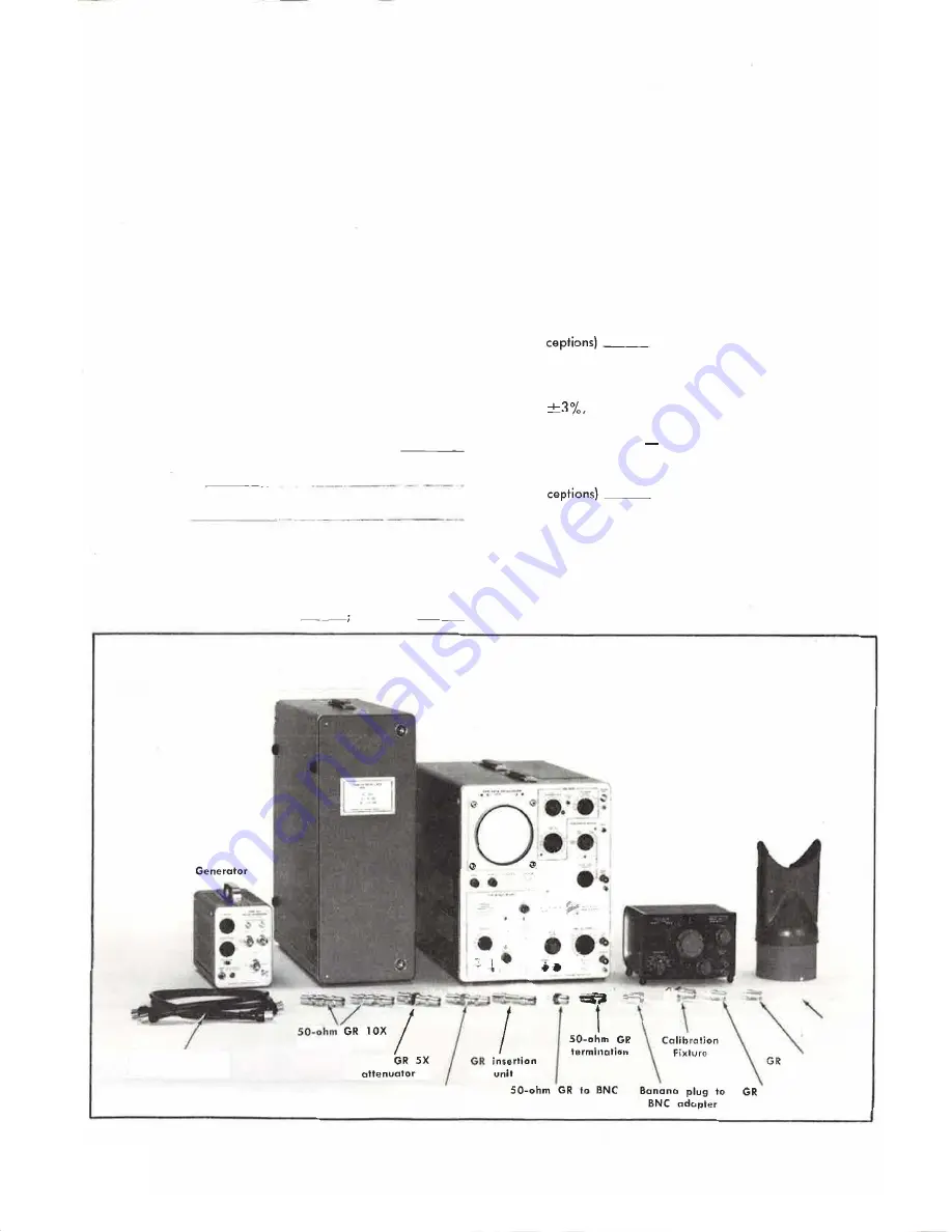
14. Insertion unit. Connectors, GR. Tektronix Part No.
01 7-0030-00.
1 5. Resistor. Description, 28 D,
1/2 W,
1 %. Tektronix Part
No. 323-0044-00.
1 6. Resistor. Description, 110D,
1/2W,
1 %. Tektronix
Part No. 323-01 01 -00.
17. Calibration Fixture. Description, 50-ohm terminating
current loop; connector, GR. Tektronix Part No. 067-0559-00.
18. Viewing hood. Purpose, for viewing low-intensity dis
plays on 580-series test oscilloscope. Tektronix Part No.
01 6-0001 -01 .
1 9. Adustment tool. Description, non-conducting screw
driver. Tektronix Part Nos. 003-0307-00 (handle), and 003-
0334-00 (insert).
SHORT-FORM PROCEDURE
Type P6021 Probe and Termination, Date Code
Calibration date
Calibrated by
o
1 . Adjust Current Probe (C1 3, RlO, R1 2)
REQUIREMENT: Correct adjustment (see complete
procedure).
PERFORMANCE: Correct
incorrect
60-nanosecond
delay cable
Performance Check
I
Calibration-P6021
o
2. Check/Adjust Aberrations (C22, C25, R36)
REQUIREMENT:
5 Foot Probe-Aberrations within
+3%, -3% total of 4% peak to peak during first 50
nanoseconds; +1%, -1%, total of 2% peak to peak
thereafter. 9 Foot Probe-Aberrations within +4%,
--4%, total of 5% peak to peak duri ng first 50
nanoseconds, +1 %, -1 %, total of 2% peak to peak
thereafter.
o
3. Check Risetime
REQUIREMENT: 1 0 mA/mV risetime of <6.5 nano
seconds; 2 mA/mV risetime of -:;;'6.7 nan-;;-seconds.
PERFORMANCE: Correct
___
; incorrect (list ex-
o
4. Check Sensitivity
REQUIREMENT: 2 mA/mV sensitivity of 80 millivolts,
at test oscilloscope input with 8-volt pulse
applied to Calibration Fixture; 10 mA/mV sensitivity
of 80 millivolts, +3%, at test oscilloscope input with
40-volt pulse applied to Calibration Fixture.
PERFORMANCE: Correct
___
;
incorrect (list ex-
o
5. Check Low Freuency Response
REQUIREMENT: 2 mA/mV low frequency response of
-:;;'450 hertz; 1 0 mA/mV low frequency response of
-:;;'1 20 hertz.
PERFORMANCE: Correct
_____
; incorrect (list ex-
ceptions)
___ _
Test
oscilloscope
Pu
l
s
e
Five-nanosecond
length
RG 213/U
attenuator
SO-ohm
50-ohm
GR 2X
attenuator
••
� .
.
terminotion
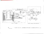
Fig. 5-1. Equipment required for calibration.
low-frequency
constant-amplitude
signal generator
.
..
.•
Viewing
hood
Adjustment
tool
to
BNC female
adopter
10
BNC male
adapter
5-2


