b. Connect a five-nonosecond length of GR 213/U co
axial cable from the remaining charge line connector to one
side of the 60-nanosecond delay cable.
c. Connect the Calibration Fixture to the pulse generator
output connector.
d. To the input of the test oscilloscope, connect a 50-ohm
GR to BNC termination, a 50-ohm GR 2X attenuator, the
insertion unit (see Fig. 5-2 for direction)' a GR to BNC female
adapter, and the P6021 Current Probe. Clamp the probe
around the conductor in the Calibration Fixture and move
the slider all the way forward.
e. Turn on the test equipment and adjust the triggering
controls, Intensity, and pulse generator amplitude to obtain
a four-centimeter display. (If necessary, use the viewing
hood on the test oscilloscope.) Position the top of the dis
play within the CRT viewing area.
f. ADJUST -Cl3, R10, and R12 (see Fig. 5-3A) for mini
mum aberrations and best flat-top response.
Performance Check
I
Calibration-P6021
b. CHECK-CRT display for risetime of :S;6.5 na
onds (with 580-series test oscilloscope operating
nosec-
within
specification). See Fig. 5-4A.
posi-
c. Set the termination slide switch to the 2 mA/mY
tion, and adjust the amplitude of the pulse generat or out-
put for four centimeters of deflection.
d. CHECK-CRT display for risetime of :S;6.7 na
onds (with 580-series test oscilloscope operating
specification). See Fig. 5-4B.
--+-l l
�
0.65
cm
nosec-
within
g. Remove the 50-ohm termination, 2X attenuator, in-
(A)
sertion unit, and the GR to BNC adapter.
2.
Checkl Adjust Aberrations
a. Connect the P6021 Termination to the input of the
test oscilloscope. Set the termination slide switch to the
2 mA/mY position.
b. Connect the P6021 Probe from the Calibration Fixture
to the termination.
c. Adjust the pulse generator output amplitude for four
centimeters of deflection. Position the top of the display
within the CRT viewing area.
d.
CHECK-5
Foot Probe-First
50
nanoseconds of step
for aberrations within +3%, -3%, total of 4% peak to peak;
+1 %, -1 %, total of 2% peak to peak after the first
50
nanoseconds (not including effects of the test oscilloscope).
9 Foot Probe-First
50
nanoseconds of step for aberrations
within +4%, -4%, total of 5% peak to peak. +1%, -1%,
total of 2% peak to peak after the first
50
nanoseconds (not
including the effects of the test oscilloscope).
e. ADJUST-C22, C25, and R36 (see Fig. 5-3C) for aber
rations within + 3%, -3%, total of 4% peak to peak dur
ing first 50 nanoseconds; +1%, -1 %, total of 2% peak
to peak after the first 50 nanoseconds (not including effects
of the test oscilloscope).
f. Set the termination slide switch to the 10 mAl mY posi
tion and increase the amplitude of the pulse generator out
put for four centimeters of deflection. Position the top of
the display within the CRT viewing area.
g. CHECK-First 50 nanoseconds of step for aberrations
within +3%, -3%, total of 4% peak to peak; + 1 %, -1 %,
total of 2% peak to peak after first 50 nanoseconds (not
including effects of the test oscilloscope). See Fig. 5-3B.
3.
Check Risetime
a. Turn on the test oscilloscope 5X magnifier and posi
tion the leading edge of the display near the center of the
CRT.
1 1
--+-
1 1�0.67
cm
(8)
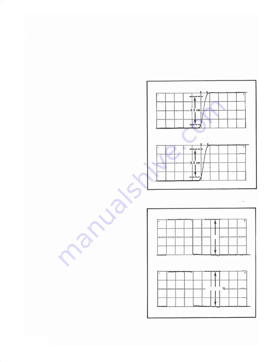
Fig. 5-4. Risetime check showing (A) within 6.5 nanosec
10
rnA/mY, and
(8)
within
6.7
nanoseconds at 2 rnA/mY
onds at
4 cm
(A)
4 cm, ± 3
(8)
eflection
Fig. 5-5. Sensitivity check showing (A) four-division d
from voltage source, and
(8)
current probe and terminat ion de-
flection of four divisions,
± 3 %.
5-4


