Fig. 2-2. Current flow in a conductor.
High Currents
When measuring high currents, do not leave the current
probe clamped around the conductor while disconnecting
the probe cable from the termination. With the probe cable
unterminated in this condition, a high voltage is developed
in the secondary winding which may damage the current
probe transformer.
Increasing the Sensitivity
The current sensitivity of the P6021 Current Probe and
Termination can be increased by increasing the number of
turns passing through the core of the probe. For example,
if the conductor is looped through the probe two times, a
two-turn primary winding is formed, increasing the second
ary current by a factor of two. (The ratio of current in a
transformer is inversely proportional to the turns ratio.) With
the P6021 Termination switch set to 2 mA/mY and the os
cilloscope vertical deflection factor set to 10 mY /div, the
deflection factor is actually reduced by a factor of two to
10 mA/div.
Remember, however, that the impedance reflected into
the primary (circuit being measured) from the secondary
(probe winding) varies as the square of the primary turns.
When observing high-frequency current waveforms or fast
rise pulses, the inductance added to the primary circuit by
the additional turns may be significant.
Insertion Impedance
The insertion impedance of the current probe is the equiv
alent circuit which is placed in the circuit under test when
Operating Instructions-P6021
2.8
pH
1 .7 nH
.004
n
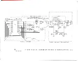
Fig. 2-3. Insertion impedance of the P6021 Current Probe.
the probe is clamped around a conductor. When observing
fast-rise signals, this should be taken into consideration.
Fig. 2-3 illustrates the approximate insertion impedance of
the P602 1 Current Probe.
Probe Shielding
The current probe is shielded to minimize the effect of
external magnetic fields. However, strong fields may in
terfere with a current signal being measured. If you suspect
that an external field is interfering with your measurement,
remove the probe from the conductor and place it in the
vicinity of the original measurement. If you obtain appreci
able deflection, attempt to measure the conductor current at
another point, away from the magnetic field source.
If current measurements must be made in the presence of
a strong external field, the external field interference may
be minimized by the use of two current probes and a dif
ferential-input oscilloscope. Both current probes must be
connected to the oscilloscope inputs in the same manner,
using P6021 Termination.
With both probes connected to a differential-input oscil
loscope, clamp one probe around the conductor in which
the current is to be measured, and place the other probe
near the first, with the slider closed. By setting the oscillo
scope controls for common-mode rejection, the undesirable
current signal induced in one probe can be minimized by the
induced current in a second probe. Adjust the positions of
the probes for best results. Complete cancellation of the
undesirable signal may be difficult to obtain due to probe
and termination differences.
2-2


