P6106A Passive Probe
P6106A Instruction Manual
5
A passive probe is capacitive for high-frequency signals. For most circuits, the
high input resistance of a passive probe has a negligible effect on the signal. The
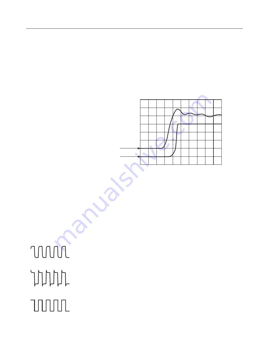
series inductances represented by the probe tip and ground lead, however, can
result in a parasitic resonant circuit that may “ring” within the bandwidth of the
oscilloscope. If the ringing is at a frequency within the oscilloscope bandwidth,
the ringing appears on the oscilloscope display as a distortion of the true
waveform. Figure 2 shows the effect on the same signal through the same probe
with different ground leads.
Long Ground Lead
Short Ground Lead
Figure 2: Signal Distortion Introduced by Ground Lead Inductance
Reducing the ground lead inductance will raise the resonant frequency. Ideally,
the inductance is low enough that the resulting frequency is above the frequency
at which you want to take measurements. To maintain the best signal integrity,
use the shortest possible ground lead and signal input path.
Passive probes require compensation to ensure maximum distortion-free output
and to avoid high-frequency amplitude errors.
Because of variations in oscilloscope input characteristics, probe low-frequency
(LF) compensation may need adjustment after moving the probe from one
oscilloscope to another. Verify the compensation before making critical rise time
or amplitude measurements.
If a 1-kHz calibrated square wave displayed at 1 ms/division shows significant
differences between the leading and trailing edges (see figures at left), perform
the following steps to optimize low-frequency compensation.
1. Connect the probe tip to a calibration signal. Most oscilloscopes have a front
panel test point for this purpose; if yours does not, use a signal generator that
produces a well-formed square wave at approximately 1 kHz.
Undercompensated
Overcompensated
Properly Compensated
Low-Frequency Probe
Compensation


