P6106A Passive Probe
6
P6106A Instruction Manual
2. Press AUTOSET (on many Tektronix oscilloscopes) or otherwise adjust the
oscilloscope so that it displays a waveform similar to those shown in this
section.
Optional: If your oscilloscope has a limited-bandwidth mode, enable it.
Filtering out high-frequency noise will make the adjustment easier to
perform.
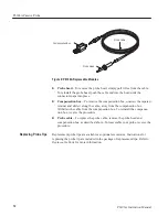
3. Adjust the trimmer in the probe (refer to Figure 3) until you see a flat-top
square wave on the display.
Figure 3: P6106A Probe Trimmer Adjustment
The probe high-frequency compensation should seldom require adjustment;
however, your probe may require high-frequency adjustment if any of the
following are true:
H
the probe has excessive high-frequency aberrations
H
the probe does not perform at the rated bandwidth
H
you have installed the probe on an oscilloscope having an input capacitance
near the limits of the probe compensation range (see Table 1 on page 8)
To perform the high-frequency compensation adjustment you will need a signal
source that has all of the following characteristics:
H
square-wave output at 1 MHz
H
fast rise output with rise time less than 1 ns
H
output terminated into 50
W
load
High-Frequency Probe
Compensation


