Service Guide
67
8.
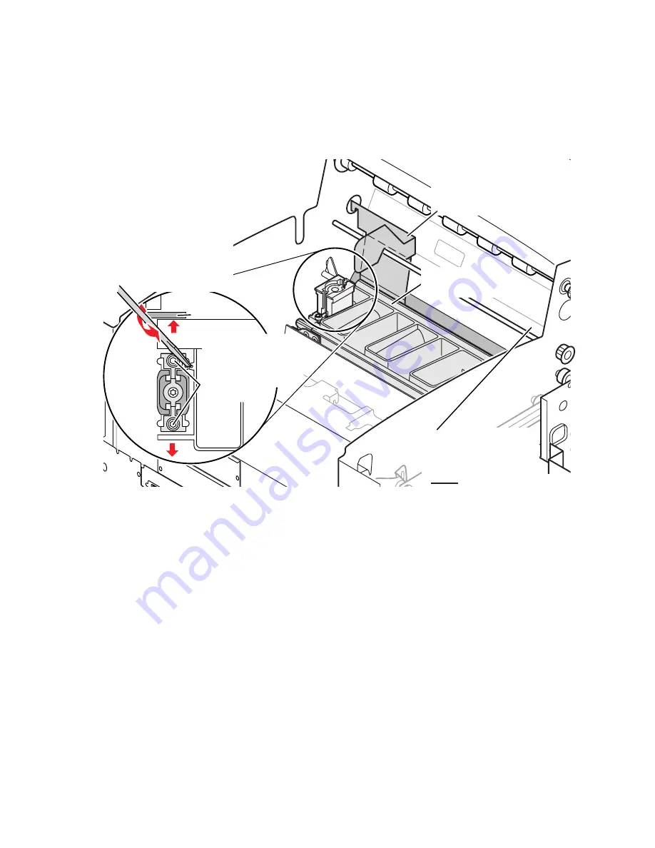
At the right side of the printhead, insert the RIGHT printhead spacer
between the printhead and the drum. Check the indicator; for a “hot
adjustment” it should read 0.0070
+
/
-
0.0010 inches, and 0.0030
+
/
-
0.0010 inches for a “cold” adjustment. Adjust the printhead’s spacing
adjustment screws until the indicator reads the correct value.
Note
Do not insert both spacers at the same time as this will only
measure the larger of the two gaps.
9.
Remove the right printhead spacer and install the LEFT spacer between
the printhead and drum. Repeat the adjustment.
10.
Remove the spacer. Snug the four locking screws using an X-pattern.
Then tighten the four screws, using the same X-pattern, to 20 in./lbs.
11.
If not connected, plug the printhead’s data ribbon cable and power
wiring harness into the power control board. Inspect both ends of the
data ribbon cable to ensure they are properly seated.
12.
Recheck the gap at both ends of the printhead.
13.
Remove the head-to-drum gap indicator and bracket from the frame.
14.
Reinstall the ink loader and metal heat cover.
15.
Select complete from the front panel. Reinstall the top cover.
16.
Print service test print Head to Drum Gap to check alignment.
Spacing the printhead to the drum
RIGHT
Tighten locking
screws when
both left and right
adjustments are
complete
Gap tool
Insert flatblade
screwdriver in
adjusting slot.
Use a twisting
motion to move
the printhead.
Position gap tool
between the printhead
and drum, hook in side
frame and over shaft
0388-31
Repeat adjustment
at this end of
printhead with
LEFT gap tool
Printhead in
print position
Summary of Contents for Phaser 840
Page 46: ...36 Phaser 840 Color Printer ...
Page 95: ...Service Guide 85 Clearing PostScript NVRAM menu item ...
Page 96: ...86 Phaser 840 Color Printer ...
Page 121: ...Service Guide 111 Figure 1 Cabinet FRUs 7 5 6 8 1 2 4 0388 21 3 ...
Page 125: ...Service Guide 115 Figure 3 Paper path FRUs 0388 16 2 1 5 11 10 9 12 6 4 3 7 13 8 ...
Page 127: ...Service Guide 117 Figure 4 Motors and fans FRUs 0388 14 7 4 3 5 6 2 1 ...
Page 129: ...Service Guide 119 Figure 5 Circuit boards FRUs 4 3 5 2 1 9 7 6 8 10 11 13 0388 13 12 ...
Page 131: ...Service Guide 121 Figure 6 Solenoids and clutches FRUs 4 5 3 2 1 0388 23 ...
Page 137: ...Service Guide 127 Figure 9 High capacity PaperTray 0388 65a 1 2 ...
Page 142: ...132 Phaser 840 Color Printer ...
Page 154: ...144 Phaser 840 Color Printer ...


