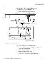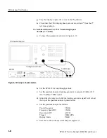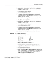
Adjustment Procedure:
SPG 422 Service Manual (B034000 and above)
5–3
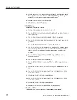
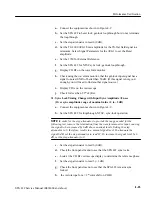
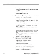
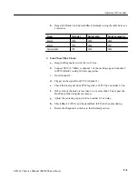
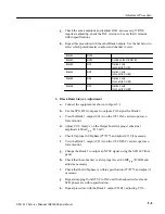
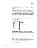
h. Repeat for Black 2 and System Black (Genlock) using the table below as
a reference.
ÁÁÁÁÁÁÁÁ
Á
ÁÁÁÁÁÁ
Á
ÁÁÁÁÁÁÁÁ
Signal
ÁÁÁÁÁÁ
Á
ÁÁÁÁ
Á
ÁÁÁÁÁÁ
Test point
ÁÁÁÁÁÁ
Á
ÁÁÁÁ
Á
ÁÁÁÁÁÁ
Null capacitor
ÁÁÁÁÁÁÁ
Á
ÁÁÁÁÁ
Á
ÁÁÁÁÁÁÁ
Centering capacitor
ÁÁÁÁÁÁÁÁ
Á
ÁÁÁÁÁÁ
Á
ÁÁÁÁÁÁÁÁ
Black 1
ÁÁÁÁÁÁ
Á
ÁÁÁÁ
Á
ÁÁÁÁÁÁ
TP10
ÁÁÁÁÁÁ
Á
ÁÁÁÁ
Á
ÁÁÁÁÁÁ
C229
ÁÁÁÁÁÁÁ
Á
ÁÁÁÁÁ
Á
ÁÁÁÁÁÁÁ
C230
ÁÁÁÁÁÁÁÁ
ÁÁÁÁÁÁÁÁ
Black 2
ÁÁÁÁÁÁ
ÁÁÁÁÁÁ
TP11
ÁÁÁÁÁÁ
ÁÁÁÁÁÁ
C236
ÁÁÁÁÁÁÁ
ÁÁÁÁÁÁÁ
C237
ÁÁÁÁÁÁÁÁ
ÁÁÁÁÁÁÁÁ
System Black
ÁÁÁÁÁÁ
ÁÁÁÁÁÁ
TP9
ÁÁÁÁÁÁ
ÁÁÁÁÁÁ
C243
ÁÁÁÁÁÁÁ
ÁÁÁÁÁÁÁ
C244
3. Fine Phase Filter Check
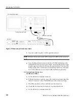
a. Keep the Diagnostic switch (S1) in 31 hex.
b. Connect TP19 (27 MHz) to channel 1 of the oscilloscope and channel 2
to TP10 (Black 1) using 500
Ω
scope probes.
c.
Invert channel 2.
d. Trigger on the signal from TP19 (channel 1).
e.
Check that the signal from TP10 lags that of TP19 by a nominal 2.2 ns.
f.
If the value of the delay is less than 3 ns or more than 10 ns, repeat the
Fine Phase Filter Adjustment (above).
g. Adjust the centering capacitor for a nominal 6.5 ns delay.
h. Check Black 2 (TP11) and System Black (TP9) for the same timing.
i.
Return the Diagnostic switches to their default position.
Summary of Contents for SPG 422
Page 4: ......
Page 14: ...Service Safety Summary x SPG 422 Service Manual B034000 and above ...
Page 17: ......
Page 62: ......
Page 67: ......
Page 92: ......
Page 96: ...Performance Verification 4 4 SPG 422 Service Manual B034000 and above ...
Page 102: ...Performance Verification 4 10 SPG 422 Service Manual B034000 and above ...
Page 136: ...Performance Verification 4 44 SPG 422 Service Manual B034000 and above ...
Page 137: ......
Page 144: ......
Page 158: ...Maintenance 6 14 SPG 422 Service Manual B034000 and above ...
Page 159: ......
Page 162: ......
Page 223: ...9 3 SPG 422 Service Manual SPG 422 Component Digital Sync Generator FRONT PANEL 1 ...
Page 224: ...SPG 422 Service Manual 9 4 ...
Page 226: ...SPG 422 Service Manual 9 6 A2 Digital Board Static Sensitive Devices See Maintenance Section ...
Page 227: ...9 7 SPG 422 Service Manual SPG 422 Component Digital Sync Generator CPU 1 ...
Page 228: ...SPG 422 Service Manual 9 8 A7 Serial Filter ...
Page 229: ...9 9 SPG 422 Service Manual SPG 422 Component Digital Sync Generator CPU I O 2 ...
Page 230: ...SPG 422 Service Manual 9 10 ...
Page 232: ...SPG 422 Service Manual 9 12 ...
Page 234: ...SPG 422 Service Manual 9 14 ...
Page 236: ...SPG 422 Service Manual 9 16 ...
Page 238: ...SPG 422 Service Manual 9 18 ...
Page 239: ...9 19 SPG 422 Service Manual SPG 422 Component Digital Sync Generator 108 MHz OSCILLATOR 7 ...
Page 240: ...SPG 422 Service Manual 9 20 ...
Page 241: ...9 21 SPG 422 Service Manual SPG 422 Component Digital Sync Generator FINE PHASE 8 ...
Page 242: ...SPG 422 Service Manual 9 22 ...
Page 244: ...SPG 422 Service Manual 9 24 ...
Page 250: ...SPG 422 Service Manual 9 30 ...
Page 252: ...SPG 422 Service Manual 9 32 ...
Page 254: ...SPG 422 Service Manual 9 34 ...
Page 256: ...SPG 422 Service Manual 9 36 ...
Page 258: ...SPG 422 Service Manual 9 38 ...
Page 260: ...SPG 422 Service Manual 9 40 ...
Page 264: ...SPG 422 Service Manual 9 44 ...
Page 265: ...9 45 SPG 422 Service Manual 53654 48 1018 2 94 4 7 857 PART OF A5 OPTION 1 BOARD ...
Page 266: ...SPG 422 Service Manual 9 46 ...
Page 268: ...SPG 422 Service Manual 9 48 ...
Page 270: ...SPG 422 Service Manual 9 50 ...
Page 274: ...SPG 422 Service Manual 9 54 ...
Page 276: ...SPG 422 Service Manual 9 56 ...
Page 277: ......
Page 278: ......
Page 286: ...SPG 422 Service Manual 10 8 ...

