background image

Summary of Contents for VX4234

Page 1: ...User Manual VX4234 Digital Multimeter Module 070 9139 02 This document applies for firmware version 1 00 and above...

Page 2: ......

Page 3: ......

Page 4: ......

Page 5: ......

Page 6: ......

Page 7: ...und Before making connections to the input or output terminals of the product ensure that the product is properly grounded To avoid electric shock or fire hazard do not operate this product with cover...

Page 8: ...loss of life CAUTION Caution statements identify conditions or practices that could result in damage to this product or other property These terms may appear on the product DANGER indicates an injury...

Page 9: ...General Safety Summary VX4234 v The following symbols may appear on the product DANGER High Voltage Protective Ground Earth Terminal ATTENTION Refer to Manual Double Insulated Symbols on the Product...

Page 10: ...of rendering first aid and resuscitation is present To avoid electric shock disconnect the main power by means of the power cord or if provided the power switch Dangerous voltages or currents may exis...

Page 11: ......

Page 12: ......

Page 13: ......

Page 14: ......

Page 15: ......

Page 16: ......

Page 17: ......

Page 18: ......

Page 19: ...15 Hz 25 Hz 25 Hz 50 Hz 50 Hz 7 5 kHz 7 5 kHz 12 kHz 12 kHz 20 kHz 15 Hz 25 Hz 25 Hz 50 Hz 50 Hz 7 5 kHz 7 5 kHz 12 kHz 12 kHz 20 kHz 15 Hz 25 Hz 25 Hz 50 Hz 50 Hz 7 5 kHz 7 5 kHz 12 kHz 12 kHz 20 kHz...

Page 20: ...5 kHz 7 5 kHz 12 kHz 12 kHz 20 kHz 15 Hz 25 Hz 25 Hz 50 Hz 50 Hz 7 5 kHz 7 5 kHz 12 kHz 12 kHz 20 kHz 15 Hz 25 Hz 25 Hz 50 Hz 50 Hz 7 5 kHz 7 5 kHz 12 kHz 12 kHz 20 kHz AC Current Range Maximum Value...

Page 21: ...aximum Value Overrange Value 200 ohm 2 Kohm 20 Kohm 200 Kohm 20 Mohm 2 Mohm 1 mA 1 mA 100 A 10 A 1 A 0 1 A 0 14 0 03 ohm 0 08 0 3 ohm 0 08 3 ohm 0 14 300 ohm 0 98 3000 ohm 0 08 30 ohm not specified no...

Page 22: ......

Page 23: ......

Page 24: ......

Page 25: ......

Page 26: ......

Page 27: ......

Page 28: ......

Page 29: ......

Page 30: ......

Page 31: ......

Page 32: ......

Page 33: ......

Page 34: ......

Page 35: ......

Page 36: ......

Page 37: ......

Page 38: ......

Page 39: ......

Page 40: ......

Page 41: ......

Page 42: ......

Page 43: ......

Page 44: ......

Page 45: ......

Page 46: ......

Page 47: ......

Page 48: ......

Page 49: ......

Page 50: ......

Page 51: ......

Page 52: ......

Page 53: ......

Page 54: ......

Page 55: ......

Page 56: ......

Page 57: ......

Page 58: ......

Page 59: ......

Page 60: ......

Page 61: ......

Page 62: ......

Page 63: ......

Page 64: ......

Page 65: ......

Page 66: ......

Page 67: ......

Page 68: ......

Page 69: ......

Page 70: ......

Page 71: ......

Page 72: ...ent Following the table you will be given instructions for interconnecting the VX4234 under test and for checking the performance parameters Results may be recorded on a photocopy of the Test Record o...

Page 73: ...le test equipment as specified in Table 1 to directly check warranted characteristics You may use instrumentation other than the recommended example if it meets the minimum requirements Table 1 Requir...

Page 74: ...ager for the VX4234 under test Tektronix VX1410 IntelliFrame Provides power cooling and backplane for VXIbus modules 2 Slot 0 Resource Manager Resource Mgr Slot 0 Functions IEEE 488 GPIB Interface VX4...

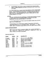
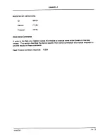
Page 75: ...rification S1 Passed Failed DC Voltage Accuracy 20 mV Range R1 0 04 14 uV Calibrator 18 0000 mV 0 00000 mV 18 0000 mV Max 018021 000014 017979 Measure Min 017979 000014 018021 200 mV Range R2 0 04 40...

Page 76: ...Mode Rejection 115 dB DC 1 kW unbalance 125 dB 50 60 Hz DC Current Accuracy 200 mA Range R1 0 04 14 mA Calibrator 180 000 mA 10 000 mA 180 000 mA Max 00019407 00002400 00016592 Measure Min 00016592 00...

Page 77: ...Hz 18208 17792 2 0 V Range R3 0 6 6 mV 1 80000 V 6 kHz 1 8168 1 7832 20 0 V Range R4 0 6 80 mV 18 0000 V 6 kHz 18 188 17 812 200 0 V Range R5 0 6 30 mV 180 000 V 6 kHz 181 88 178 12 700 0 V Range R6 0...

Page 78: ...light will be off and SYSFAIL will be asserted Following a successful VXIbus system startup sequence the green PWR light on the VX4234 front panel indicates that the self test has passed and that the...

Page 79: ...on If you are using a different Controller perform the equivalent function to confirm the responses shown in Table 5 Your configuration may not be identical but the information should be the same Tabl...

Page 80: ...e to the limits shown in the Test Record set VX4234 ibwrt F1R1 ibrd 100 Observe 01800 0 0000212 VDC see Table 6 5 Set the Calibrator to 18 0 mV DC 6 Re acquire and verify the response to the limits sh...

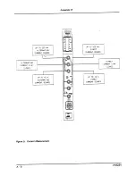
Page 81: ...ent Requirements Calibrator item 1 Coaxial Cable one item 2 Dual Banana Connectors two item 3 Binding Post Connector item 5 Clip Lead Connector item 6 1 k Resistor Watt 5 Prerequisites All prerequisit...

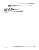
Page 82: ...0018 5 Set the Calibrator to 100 0 V 50 or 60 Hz Perform two acquisitions and verify the second response to be 56 8 mV ibrd 100 Disregard this reading ibrd 100 Observe 3 000056 6 Set the Calibrator to...

Page 83: ...ator to 10 0 V 50 Hz 8 Perform two acquisitions and verify the second response to be 2 24 mV ibrd 100 Disregard this reading ibrd 100 Observe 3 002239 9 Set the Calibrator to 0 0000 mV DC 10 Reset the...

Page 84: ...the first entry in Table 7 is a repeat of steps 3 through 7 above Table 7 DC Current Accuracy Set Calibrator Command to VX4234 Response to Verify 180 000 mA 180 000 mA Steps 3 to 7 repeated for conti...

Page 85: ...item 2 Prerequisites All prerequisites listed on page A 22 1 Set the Calibrator to 180 000 mV and 6 0 kHz 2 Connect the Calibrator to the VX4234 Voltage input using two Dual Banana connectors and a C...

Page 86: ...ges Equipment Requirements Calibrator item 1 Coaxial Cable two item 2 Dual Banana Connectors four item 3 Prerequisites All prerequisites listed on page A 22 1 Set the Calibrator to 100 2 Connect the C...

Page 87: ...alibrator Command to VX4234 Response to Verify 100 000 Step 4 repeated for continuity ibwrt F4R1 ibrd 100 100 17 to 99 83 1000 00 ibwrt R2 ibrd 100 1001 1 to 998 9 10 0000 k ibwrt R3 ibrd 100 10011 0...

Page 88: ...re for use only by qualified personnel To avoid injury do not perform any servicing other than that stated in the operating instructions unless you are qualified to do so Refer to all Safety Summaries...

Page 89: ...37...

Page 90: ...38 Appendix G...

Page 91: ...39 Appendix G...

Page 92: ...40 Appendix G...

Reviews: