background image

Appendix I: Performance Verification

A–64

VX4790A Arbitrary Waveform Generator Module

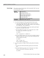
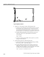
This sequence verifies the functionality of the front panel EXT TRG* input and
the VXIbus TTLTRG* signals.

Equipment
Requirements

Oscilloscope (item 1)

Oscilloscope Probe (item 2)

VX4750 external clock source (item 4 )

SMB to BNC cable, two required (item 5)

BNC to BNC barrel adaptor (item 9)

BNC to BNC cable (item 6)

50 

W

 BNC Feed Through Termination (item 8)

Prerequisites

All prerequisites listed on page A–46

1. To verify the front panel EXT TRG input perform the following steps:

a. Connect the VX4790A ARB OUT signal to CH1 of the oscilloscope

using an SMB to BNC cable and a 50 

W

 Terminator. Set the oscilloscope

for a 1 M

W

 input, 5 V/div, and 500 

µ

s/div.

b. Connect the VX4750 TRIG OUT signal to the VX4790A  EXT TRIG*

input with a second SMB to BNC cable.

c.

Reset the VX4790A to generate a 

±

5 V, 1 kHz square wave, to enable

the external trigger, and enable the output relay.

set VX4790

ibwrt "k;setsquare 5 -5 1000;1x;1o"

d. Reset the 

VX4750

 to generate a sine wave which concurrently generates a

trigger on the TRIG OUT connector. Verify on the oscilloscope that the
VX4790A triggers concurrently.

set VX4750

ibwrt "rst;wave sine"


(Observe initiation of square wave)

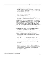
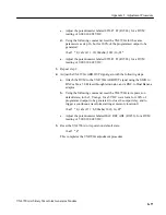
2. To verify recognition of VXIbus TTLTRG* signals perform the following

steps:

a. Disconnect theVX4790A EXT TRIG input from the VX4750 TRIG

OUT

b. Reset the VX4790A to generate a 

±

5 V, 1 kHz square wave, enable a

trigger from TTLTRG0*, and enable the output relay.

set VX4790

External Trigger

Summary of Contents for VX4790A

Page 1: ...document applies for firmware version 1 00 and above Warning The servicing instructions are for use by qualified personnel only To avoid personal injury do not perform any servicing unless you are qu...

Page 2: ...ign patents issued and pending Information in this publication supercedes that in all previously published material Specifications and price change privileges reserved Printed in the U S A Tektronix I...

Page 3: ...any other locations This warranty shall not apply to any defect failure or damage caused by improper use or improper or inadequate maintenance and care Tektronix shall not be obligated to furnish ser...

Page 4: ...al of the European Communities EN 55011 Class A Radiated and Conducted Emissions EN 50081 1 Emissions EN 60555 2 AC Power Line Harmonic Emissions EN 50082 1 Immunity IEC 801 2 Electrostatic Discharge...

Page 5: ......

Page 6: ......

Page 7: ...Module Commands 3 3 Summary 3 4 Command Descriptions 3 8 SYSFAIL Self Test and Initialization 3 73 Synchronizing Multiple Instrumentation Modules 3 74 Section 4 Programming Examples Definition of BASI...

Page 8: ...Table of Contents ii VX4790A...

Page 9: ...shock or fire hazard do not operate this product with covers or panels removed To avoid fire hazard use only the fuse type and rating specified for this product To avoid electric shock do not operate...

Page 10: ...indicates an injury hazard not immediately accessible as you read the marking CAUTION indicates a hazard to property including the product The following symbols may appear on the product Protective G...

Page 11: ......

Page 12: ......

Page 13: ......

Page 14: ......

Page 15: ......

Page 16: ......

Page 17: ......

Page 18: ...uV...

Page 19: ......

Page 20: ......

Page 21: ......

Page 22: ......

Page 23: ......

Page 24: ......

Page 25: ......

Page 26: ......

Page 27: ......

Page 28: ......

Page 29: ......

Page 30: ......

Page 31: ......

Page 32: ......

Page 33: ......

Page 34: ......

Page 35: ......

Page 36: ......

Page 37: ......

Page 38: ......

Page 39: ......

Page 40: ......

Page 41: ......

Page 42: ......

Page 43: ......

Page 44: ......

Page 45: ......

Page 46: ......

Page 47: ......

Page 48: ......

Page 49: ......

Page 50: ......

Page 51: ......

Page 52: ......

Page 53: ......

Page 54: ......

Page 55: ......

Page 56: ......

Page 57: ......

Page 58: ......

Page 59: ......

Page 60: ......

Page 61: ......

Page 62: ......

Page 63: ......

Page 64: ......

Page 65: ......

Page 66: ......

Page 67: ......

Page 68: ......

Page 69: ......

Page 70: ......

Page 71: ......

Page 72: ......

Page 73: ......

Page 74: ......

Page 75: ......

Page 76: ......

Page 77: ......

Page 78: ...al The frequency and attenuation which was actually programmed may be obtained with the GETFREQ and GETATT commands respectively Note that the GETFREQ command returns the sample frequency not the freq...

Page 79: ......

Page 80: ......

Page 81: ......

Page 82: ......

Page 83: ......

Page 84: ......

Page 85: ......

Page 86: ......

Page 87: ......

Page 88: ......

Page 89: ......

Page 90: ......

Page 91: ......

Page 92: ......

Page 93: ......

Page 94: ......

Page 95: ......

Page 96: ......

Page 97: ......

Page 98: ......

Page 99: ......

Page 100: ......

Page 101: ......

Page 102: ......

Page 103: ......

Page 104: ......

Page 105: ......

Page 106: ......

Page 107: ......

Page 108: ......

Page 109: ......

Page 110: ......

Page 111: ......

Page 112: ......

Page 113: ......

Page 114: ......

Page 115: ......

Page 116: ......

Page 117: ......

Page 118: ......

Page 119: ......

Page 120: ......

Page 121: ......

Page 122: ......

Page 123: ......

Page 124: ......

Page 125: ......

Page 126: ......

Page 127: ......

Page 128: ......

Page 129: ......

Page 130: ......

Page 131: ......

Page 132: ......

Page 133: ......

Page 134: ......

Page 135: ......

Page 136: ......

Page 137: ......

Page 138: ......

Page 139: ......

Page 140: ......

Page 141: ......

Page 142: ......

Page 143: ......

Page 144: ......

Page 145: ......

Page 146: ......

Page 147: ......

Page 148: ...070 9152 02...

Page 149: ......

Page 150: ......

Page 151: ...rm the procedure General Information and Conventions Please familiarize yourself with the following conventions which apply throughout this procedure H Each test sequence begins with a table similar t...

Page 152: ...Table I 1 Required Test Equipment Item Number and Description Minimum Requirements Example Purpose 1 Digitizing Oscilloscope 300 MHz bandwidth 50 W input impedance 1 5 DC vertical accuracy with frequ...

Page 153: ...available slots one for the VX4790A and one for the Pattern Generator in addition to the Slot 0 controller Tektronix VX1401 VX1400A VX1405 VX1410 Power cooling and backplane for VXIbus modules 2 Slot...

Page 154: ...on Device GPIB De vice Name VXI Slot VXIbus Logical Address GPIB Primary Address GPIB0 GPIB0 PC card NA 30 VX4521 VX4521 Slot 0 13 0d hexadecimal 13 VX4790A under test VX4790 Slot 1 01 1 VX4750 VX4750...

Page 155: ...0 V 0 000 V 3 400 V 6 81 V 10 23 V 10 V Range Max 10 42 V 7 01 V 3 60 V 0 200 V 3 200 V 6 61 V 10 03 V Measure Min 10 02 V 6 61 V 3 20 V 0 200 V 3 600 V 7 01 V 10 43 V 5 V Range Program 5 11 V 3 41 V...

Page 156: ...Passed Attenuation 100 75 50 20 0 Modulation 1 5 VDC 0 75 VDC 0 0 VDC 0 75 VDC 1 5 VDC SYNC Out Pulse 0 V Step 1 V Step 2 V Step 3 V Step Clock and Trigger Passed Failed Phase Lock Loop 25 MHz 22 MHz...

Page 157: ...ce Verification VX4790A Arbitrary Waveform Generator Module A 51 VXIbus Trigger Triggered by VXIbus Triggered Asserted to VXIbus Passed Failed Passed Failed TTLTRG0 TTLTRG1 TTLTRG2 TTLTRG3 TTLTRG4 TTL...

Page 158: ...the assertion of SYSFAIL and module ERROR conditions The GETERR command may be used at any time during operation to determine the current state of the module Following the VXIbus system startup sequen...

Page 159: ...CII device response Just type buffer 1 1 To verify the system configuration send the TABLE command to the Slot 0 Resource Manager and confirm the responses shown in Table I 5 Your configuration may no...

Page 160: ...0A ERROR light on ibrd 0 Observe VX4521 Slot 0 2nd digit indicates S for SRQ NOTE The zero length read command serves to unaddress the Slot 0 controller allowing it to detect the VXIbus interrupt and...

Page 161: ...ARB OUT relay Then set up an output voltage of 10 22 VDC and assert a trigger z is the breakpoint and end of waveform voltage designator Verify the accuracy to be within 1 0 of full scale 200 mV set V...

Page 162: ...1 7 of full scale 3 4 mV Table I 8 0 1 V Range Verification Command to Send DC Voltage to Verify ibwrt setvoltr0 1 ibwrt q 0 1022z t 0 0988 to 0 1056 VDC ibwrt q 0 0681z t 0 0647 to 0 7150 VDC ibwrt...

Page 163: ...e set VX4790 ibwrt k 1o ibwrt setsine 5 1e3 t Observe 10 Vpp 1 kHz sine wave 3 Check the additional waveforms listed in Table I 9 Table I 9 Stored Waveform Verification Command to Send Waveform to Ver...

Page 164: ...aveform roughness 3 Reset the VX4790A to generate a 100 kHz sine wave and verify the waveform on the oscilloscope Then assert the 500 kHz lowpass filter and verify that the steps in the sine wave are...

Page 165: ...he VX4790A AM IN using a second SMB to BNC cable 3 Reset the VX4790A to its power up state and close the ARB OUT relay Set up a 10 Vp 20 Vpp 1 kHz sine wave and verify the waveform on the oscilloscope...

Page 166: ...pp sine wave ibwrt Ofst 1 5 0 0 Vpp sine wave This sequence verifies the SYNC output signal and its programmable position ing within the ARB OUT pattern memory Equipment Requirements Oscilloscope item...

Page 167: ...3w t SYNC coincident with the 2 V step ibwrt 0n 0v 1v 2v 3yw t SYNC coincident with the 3 V step This sequence verifies Phase Locked Loop frequency synthesis from 12 5 MHz to 25 MHz and frequency sca...

Page 168: ...ision function reset the VX4790A to a 5 V 25 MHz square wave Then specify a scaling integer and verify the resulting SMP CLK frequency as indicated in Table I 14 ibwrt k 0n 5v5w t 1o Observe 25 MHz sq...

Page 169: ...W input and 2 V div 3 Reset the VX4790A first memory location to a negative 5 V level the second location to a positive 5 V level enable the EXT CLK input as the sample clock close the output relay an...

Page 170: ...Terminator Set the oscilloscope for a 1 MW input 5 V div and 500 s div b Connect the VX4750 TRIG OUT signal to the VX4790A EXT TRIG input with a second SMB to BNC cable c Reset the VX4790A to generat...

Page 171: ...epetitively trigger or gate the VX4750 a Connect the VX4790A SYNC output to its EXT TRIG input using two SMB to BNC cables and a barrel connector b Connect the VX4750 FUNC OUT to CH2 of the oscillosco...

Page 172: ...66 VX4790A Arbitrary Waveform Generator Module g Check the additional TTLTRG lines by repeating steps d and e and substituting VXI in step d and 3 x in step e where the 1 2 3 4 5 6 and 7 This complet...

Page 173: ...y by qualified personnel To avoid personal injury do not perform any servicing other than that contained in the operating instructions unless you are qualified to do so Refer to General Safety Summary...

Page 174: ...tion as described in Table J 3 and that you will be using the National Instruments PC GPIB controller and software NI 488 2M The adjustment steps instruct you to issue the corresponding Interface Bus...

Page 175: ...Loading ARB OUT signal 5 VXIbus Extender Board Full length C size Tektronix 73A 850 Providing adjustment access System Requirements In order to perform this procedure the VX4790A must be installed in...

Page 176: ...lot 1 01 1 Adjustment Procedure This procedure adjusts the DC reference and offset voltages of the DAC and the Gain of the ARB OUT amplifier You may adjust the module on a VXIbus extender card or in t...

Page 177: ...ing the following commands reset the VX4790A to its power on default state and for a 100 output amplitude no attenuation ibfind VX4790 ibwrt k 100 c Adjust the potentiometer labeled MULT REF ADJ R1211...

Page 178: ...B OUT signal gain with the following steps a Attach the DVM to the VX4790A ARB OUT signal using the SMB to BNC cable a 50 W feed through terminator and a BNC to Dual Banana adaptor b Using the followi...

Page 179: ...Appendix J Adjustment Procedure A 72 VX4790A Arbitrary Waveform Generator Module...

Reviews: