background image


Energy 4010 G 

Rev. 004


GB


v. 004 – March 2018


Summary of Contents for Energy 4010G

Page 1: ...Energy 4010 G Rev 004 1 GB v 004 March 2018 ...

Page 2: ...ecting an External Network Relay 15 5 OPERATING INSTRUCTIONS 16 5 1 Machine safety 16 6 USING THE GENERATING SET 16 6 1 Starting up the generating set 16 6 2 Turning the generating sets off 17 6 3 Information on not recommended uses 17 6 4 Useful tips 17 6 5 Control and alarm functions Fig 30 17 6 6 Control panel alarm causes and resetting 17 6 7 Automatic Version optional 18 6 8 MANUAL operation ...

Page 3: ...Rev 004 Energy 4010 G 3 GB To use the generator at temperatures below 0 C we recommend to employ propane up to a mini mum temperature of 15 C ...

Page 4: ...r written ap proval Machine GENERATING SET Model ENERGY 4010 G Maximum power 3 8 KW 3000 r p m Serial number Directive of reference Machine Directive 2006 42 UE Low Voltage Directive 2014 35 UE Electro magnetic Compatibility 2014 30 UE Harmonised standards applied EN 60204 1 Directives noise emission in the environment 2005 88 CE 2000 14 CE Attachment VI procedure 1 DLGS 262 2002 Measured noise po...

Page 5: ...ng so is essential to the cor rect long term performance and reliability of the generator set and the prevention of injury and or damage Note The information contained in this publica tion was correct at the time it went to print but may be modified without advance notice 1 2 Symbols and Definitions Graphic safety symbols have been employed in this booklet to identify different levels of danger or...

Page 6: ...bracket 8 Electronic control panel 9 Gas pipe and cable outlet block 10 Sliding surface locking screw 11 Fuel pipe 12 Sliding surface all out locking screw 2 2 Identification plate Fig 2 1 Generating set model 2 Serial number 3 Frequency 4 Power factor 5 Maximum electric power 6 Maximum current 7 Rated voltage 230V AC 8 Current delivered at 12V DC 9 Weight 2 3 Overall dimensions Figure 3 shows the...

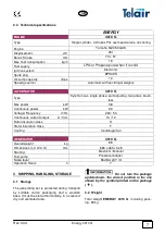
Page 7: ...tinuous power kW 3 3 Voltage Frequency V Hz 230 50 Continuous current output A Vdc 10 12 Rotor insulation class H Stator insulation class F Cooling Centrifugal fan GENERATOR 4010 G Overall weight kg 86 Dimensions L X W X H mm 665 x 465 x 345 Starting Electrical Manual Fuel pump Pressure reducer Noise level 65 dBA 7 mt Operation Hours h 7 3 SHIPPING HANDLING STORAGE 3 1 Storage The generating set i...

Page 8: ...also not be liable for any injury or damage to people or prop erty Installation must be per formed by qualified and adequately trained personnel only 4 2 Instructions for fastening the generating set The ENERGY 4010 G generating sets are pro vided with anchoring brackets with extra vibration dampers The brackets allow for hanging and floor assembly This kind of assembly provides the following ad v...

Page 9: ...ose of preventing hot air from spreading inside the generator compartment The brackets of the generator must be moved in order to fasten the Energy 4010 G on the bear ing surface On both sides remove the hole plugs fig 8 ref 1 and screw out the screws fig 8 ref 2 in order to remove the bracket fig 8 ref 3 Place the bracket fig 9 ref 3 on the 4 holes which were previously covered by the plugs us in...

Page 10: ...in Table 1 To this end the generating set is provided with two special terminals Fig 13 Ref 2 used to con nect the positive and negative poles of the bat tery Connect the cable of the positive pole red cable to the terminal already having a red cable and the cable of the negative pole black pole to the terminal already having a black cable The cable of the negative pole must be of the same cross s...

Page 11: ...s must be con nected Use the special cable outlet Fig 11 Ref 1 to prevent water seeping into the generating set Although the generating set is equipped with a special internal thermal cut out to cut power de livery in the event of overload or short circuits Fig 13 Ref 5 it is advisable to install in the ve hicle control panel a thermomagnetic cut out switch suitably set to stop power delivery to t...

Page 12: ...ct the cable black connector on the back of the electronic control panel Fix the electronic control panel Fig 14 by using 3 x 20 mm self tapping screws making sure that the rear part does not interfere with other surfaces Apply light pressure to fix the plastic frame until the anchor ing tabs click in 4 8 Electric System fuses The unit is provided with two protection fuses a 15 Ampere fuse Fig 13 ...

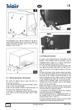
Page 13: ...re of 15 C 4 10 Battery charger ENERGY 4010 G generating sets are equipped with a battery charger which can deliver current of approximately 10 Amp at 12 V It can be used to recharge the generating set start up battery To obtain this function use a 2 5 mm2 cross section cable to connect the terminal identified by CHARG Fig 19 Ref 1 to the positive pole red cable of the generating set Fig 19 Ref 2 ...

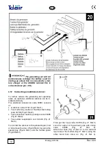
Page 14: ...f A silencer code 01761 Fig 21 Ref 1 Two metre long section of flexible steel tubing code 00705 Fig 21 Ref 2 Two connection fastening clamps code 01655 Fig 21 Ref 3 Two rubber suspenders cod 02 440 Fig 21 Ref 4 To connect the silencer to the generating set first of all remove the door Fig 22 Ref 2 by using the special key Fig 22 Ref 1 and the muffler guard Fig 22 Ref 3 Then put the hose code 00705...

Page 15: ...cle wir ing system Its purpose is to insulate the generat ing set when the vehicle is connected to an ex ternal electric input network Connect the relay Fig 29 according to the fol lowing instructions Connect the two wires of the 230 V line of the generating set to the PINS 1 3 Connect the user line to the PINS 7 9 Connect the outside line to the PINS 6 4 Jumper the PINS 4 A Jumper the PINS 6 B Co...

Page 16: ...cut out switches with others having higher amper age Should any electrical part need checking this must only be done with the engine turned off and by specialised personnel The generating sets have been built in compli ance with the safety standards listed in the EEC statement of compliance 6 USING THE GENERATING SET 6 1 Starting up the generating set The generating sets are provided with an elec ...

Page 17: ...g 75 of its rated load 6 5 Control and alarm functions Fig 30 2 Display when the generating set has started up the total running hours will be displayed Press the key provided below the control panel display unit Fig 30 Ref 9 to display the number of generating set operation hours since the latest engine oil change 3 High temperature indicator this warning light will light up when the temperature ...

Page 18: ...tor 6 Generator running indicator flashing 7 Maintenance request indicator 8 Fuel reserve indicator 9 Hour or voltmetric changeover switch button 10 Reset 11 Battery charged indicator 12 Automatic function indicator 13 AUTO MAN switch for the automatic or man ual function 6 8 MANUAL operation See section 6 1 6 9 AUTOMATIC operation Turn the AUTO MAN switch Fig 32 Ref 13 to the AUTO position and se...

Page 19: ...tion and all its parts must be cold 7 3 Checking the engine oil level All engine oil level check ing operations must be performed with the generating set in a perfectly horizontal posi tion Unscrew the engine oil filler cap and clean the dipstick Fig 33 Ref 1 Put the dipstick back in without screwing Take the dipstick out again and make sure that the engine oil level is between the two min and max...

Page 20: ...k the oil level when the engine has been turned off Spent oil should not be disposed freely in the environment but taken to special disposal centres carrying out dis posal and or recycling in compliance with the applicable law provisions in force in the country of use 7 4 2 Air filter maintenance A clogged air filter will reduce air flow to the carburettor To prevent carburettor malfunction check ...

Page 21: ...and 0 8 mm Fig 37 Correct the distance if necessary bending the side electrode Make sure that the spark plug washer is in good condition and then screw back on by hand to make sure that it is correctly put back in place Finally tighten to the right torque us ing the special wrench see instructions in the engine user and maintenance manual When assembling a new spark plug tighten by 1 2 turn after ...

Page 22: ...urn the screw counter clockwise to decrease the engine rpm and consequently the voltage 7 4 5 Adjusting the choke The choke operates at 1 and the 3 rd attempt to start and has a response time of 2 sec If you want to vary the operating time of action as in Fig 39 40 41 The adjustment can vary from 1 to 3 seconds ...

Page 23: ...Check Adjust 2 Fuel Pipe Check for leaks or cracks 2 Muffler Check for leaks or cracks 2 Clean and replace spark screen if necessary 2 2 Air Choke Valve Check correct operation 2 Engine rpm or Frequency Check Adjust 2 Vibration Damper Sus pension Points Check Replace if necessary 2 NOTES 1 Clean more frequently if you use it in a very dusty environment 2 These operations must be performed by speci...

Page 24: ...ty period shall end no later than 14 months 16 months if delivered outside of Europe after ex factory delivery In any case the costs of lubricants and consumables shall be charged Any transport expenses shall have to be covered by the purchaser the same applies to any expenses connected with inspections requested by the customer and accepted by TELAIR The manufacturer s warranty shall only be vali...

Page 25: ...Rev 004 Energy 4010 G 25 GB WIRING DIAGRAM ENERGY 4010 G ...

Page 26: ...e protection fuse Pressure reducer GAS solenoid valve GAS Wiring Protection Fuse Battery charger terminal Pos 14 15 16 17 18 19 20 21 22 23 24 25 A Description Electronic control panel Electronic control panel connector Startup relay Electronic control board Gas wiring connector Rotor Alternator Stator Condenser Power connection terminal board Thermal switch Diode bridge Alternator Connector Pos 1...

Page 27: ...Rev 004 Energy 4010 G 27 GB DRAWING FOR SPARE PARTS LIST ENERGY 4010 G ...

Page 28: ...Energy 4010 G Rev 004 28 GB ...

Page 29: ...Rev 004 Energy 4010 G 29 GB ...

Page 30: ...Energy 4010 G Rev 004 30 GB ...

Page 31: ...lierung links für Haube Aislante Izquierdo Capó 8 04589 N 1 Isolante Aletta DX Isolation DX Capot Isolatie links DX voor kap hood DX insulation Isolierung links DX für Haube DX Izquierdo Capó 9 04585 N 1 Isolante Destro Cofano Isolation Droite Capot Isolatie rechts voor kap Right hood insulation Isolierung rechts für Haube Aislante Derecho Capó 10 02666 N 2 Isolante posteriore Alette Isolante aile...

Page 32: ...iteil zum Schutz der Diodenbrücke Proteccion de caucho puente de diodos 22 04066 N 1 Piastrina di scarico Plaquette d échappement Uitlaatplaatje Exhaust plate Auslassplatte Chapa de descarga 23 02185 N 1 Chiusura scatola marmitta Fermeture du boitier du pot d èchappement Afdekking knaldemperkast Muffler box closure Verschluss Schalldampferge hause Cierre caja silenciador 24 02408 N 1 Marmitta Pot ...

Page 33: ...teur au Panneau de Contrôle 7 m kabel van generator naar bedieningspaneel 7 m cable from generating set to control panel 7 m Kabel vom Generator zum Bedienpanel Cable 7 m de generador a panel de control 37 03798 optional Cavo 10 mt da generatore a Pannello di controllo Câble 10 m du générateur au Panneau de Contrôle 10 m kabel van generator naar bedieningspaneel 10 m cable from generating set to c...

Page 34: ... x 18 DIN 6796 Arandela 8 x 18 DIN 6796 48 03103 N 4 Vite M8x14 TE Vis M8 x 14 TE Schroef M8 x 14 TE Screw M8 x 14 TE Schraube M8 x 14 TE Tornillo M8 x 14 TE 49 04465 N 2 Staffa Fissaggio Generatore Étrier Fixation du Générateur De Inplanting van de stijgbeugel van de Generator Bracket Implantation of the Gen erator Steigbügel Einpflanzung des Generators Implantación del estribo del generador 50 0...

Page 35: ...sluitklem LEGRAND 25mmq Terminal Legrand 25sq mm Klemme LEGRAND 25mmq Borne LEGRAND 25mmq 63 01139 N 1 Morsetto Muller 3 12 Borne Muller 3 12 Aansluitklem Muller 3 12 Terminal Muller 3 12 Klemme Muller 3 12 Mordaza Muller 3 12 65 03440 N 3 Distanziale Esagonale M3x8 Entretoise Hexagonale M3x8 Zeskantafstandshouder M3x8 Hexagonal M3x8 spacer Distanzstück Sechskant M3x8 Separador Hexagonal M3x8 66 0...

Page 36: ...Fundicion ATR 4000 B1 76 03574 N 1 Ventola Ventilateur Ventilator Fan Lufterrad Ventilador 77 02183 N 1 Convogliatore alternatore Convoyeur alternateur Geleider wisselstroomdynamo Alternator conveyor Luftleitblech Lichtmaschine Transportador alternador 78 02614 N 1 Distanziale ventola Entretoise du ventilateur Afstandshouder ventilator Fan spacer Distanzstuck Lufter Riostra ventilador 79 03573 N 1...

Page 37: ...erraggio Douille de serrage Klemmoer Locking ring nut Befestigungsschraube Virola de apretado 95 03422 N 1 Anello di serraggio Bague de serrage Klemring Locking ring Arretierring Anillo de apretado 96 03855 N 1 Tubo raccordo GAS Tuyau de raccord GAZ GAS aansluitpijp GAS union pipe GAS Anschlussleitung Tubo conexión GAS 97 03834 N 1 Raccordo GAS a 90 Raccord GAZ à 90 GAS aansluiting 90 GAS union el...

Page 38: ...Dop Cap Kappe Tapón 105 04042 N 1 Raccordo uscita GAS Raccordo uscita GAS GAS uitlaatkoppeling GAS output fitting GAS output fitting Conexión salida GAS 106 05080 N 1 Riduttore Pressione GAS completo Manodétendeur GAZ complète GAS drukregelaar compleet GAS pressure reducer com plete GAS Druckreduzierer komplett Reductor Presión GAS completo 107 04705 N 1 Raccordo a 90 Raccord à 90 90 aansluitpijp ...

Page 39: ...Rev 004 Energy 4010 G 39 GB Notes ...

Page 40: ...Energy 4010 G Rev 004 40 GB ...

Reviews: