TIG 3000 G
Vers. 001
12
GB
the pipe (fig. 13 ref. 4), and tighten the clamp. Fix
the silencer using the threaded couplings (fig. 13
ref. 6) and secure the flex hose, making sure
there is no obstruction to generator extraction for
routine maintenance purposes.
4.4 LPG hose connection
The generator must be fuelled with
LPG in a gaseous state at a pressure of 30
mb. Higher pressures can seriously damage
the generator.
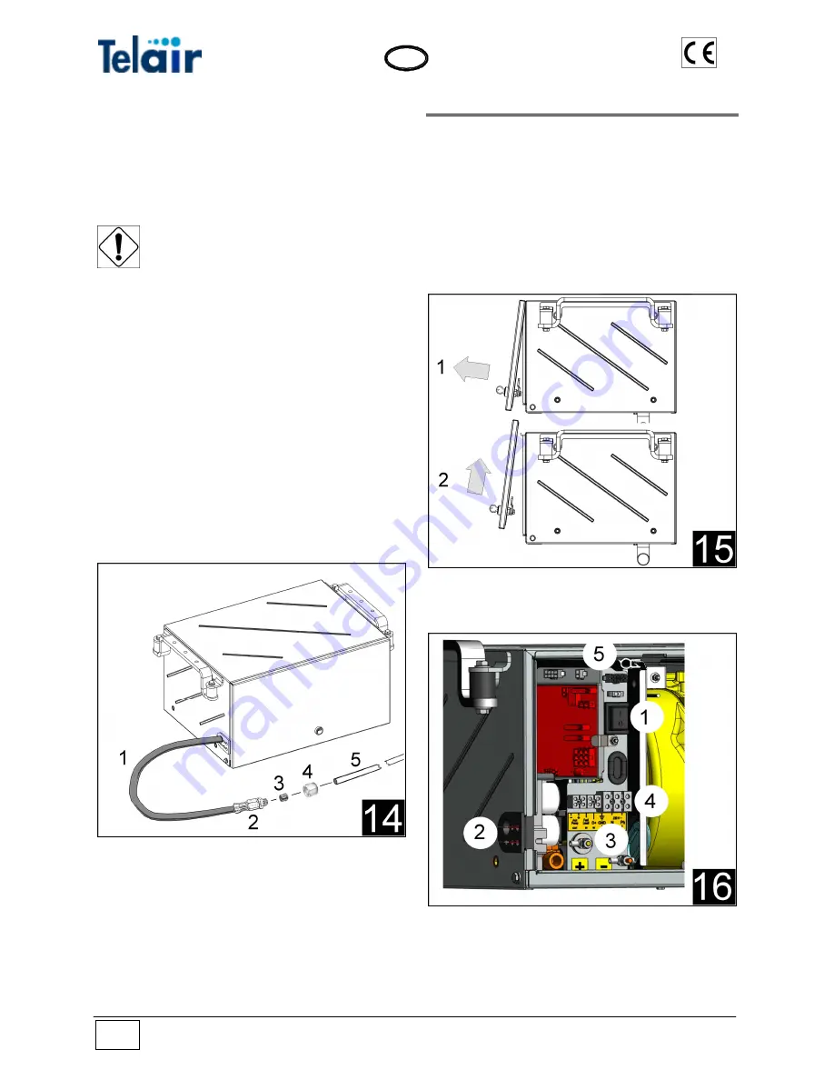
The rubber hose exits from the left side of the
generator (fig. 14 ref. 1): this is used to fuel the
engine with LPG. At the end of the hose there is
a fast connector with an ogive (diameter 8 mm)
suitable for connection to the vehicle steel piping
system as shown in the figure.
Insert the nut (fig. 14 ref.4) and the ogive (fig. 14
ref. 3) in the steel pipe (fig. 14 ref. 5) coming from
the LPG system, then tighten the nut all the way
onto the connector.
If the vehicle LPG system consists of copper pip-
ing, a D6xd5 steel reinforcement bushing must
be inserted inside the hose near the ogive.
Do not crush the rubber hose or bend it too
sharply.
If the LPG tank has a fuel reserve indicator, the
service terminal strip will have a wire connector
to connect the electrical wire coming from the
fuel sensor switch.
5 ELECTRIC WIRING CONNECTIONS
5.1 Access to internal electrical connections
To carry out electrical connections to the genera-
tor it is necessary to remove the front door.
To do this release the lock, pull the lower part of
the door outwards (fig. 15 ref. 1), then push it
upwards (fig. 15 ref. 2). Store it in a safe place
until it is refitted at the end of generator connec-
tion operations.
5.2 Safety Switch
Before starting any maintenance operations or
carrying out electrical connections inside the
generator, the safety switch must be turned to its
O (Off) position (fig.16 ref. 1). The switch must
then be turned back to its I (On) position once the
Summary of Contents for TIG 3000G
Page 6: ...TIG 3000 G Vers 001 6 GB THIS PAGE HAS BEEN LEFT BLANK INTENTIONALLY ...
Page 28: ...TIG 3000 G Vers 001 28 GB 12 TIG 3000 G WIRING DIAGRAM ...
Page 29: ...Vers 001 TIG 3000 G 29 GB ...
Page 31: ...Vers 001 TIG 3000 G 31 GB 13 TIG 3000 G SPARE PARTS LIST ...
Page 32: ...TIG 3000 G Vers 001 32 GB ...
Page 33: ...Vers 001 TIG 3000 G 33 GB ...
Page 34: ...TIG 3000 G Vers 001 34 GB ...
Page 42: ...TIG 3000 G Vers 001 42 GB Notes ...
Page 43: ...Vers 001 TIG 3000 G 43 GB ...
Page 44: ......


