GW-483S Installation Guide
Rev. B
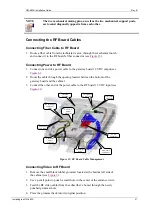
NOTE
The two mechanical mating pins, as well as the two mechanical support posts,
are located diagonally opposite from each other.
Connecting the RF Board Cables
Connecting Fiber Cable to RF Board
1.
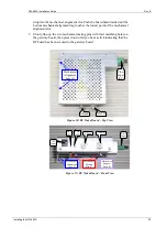
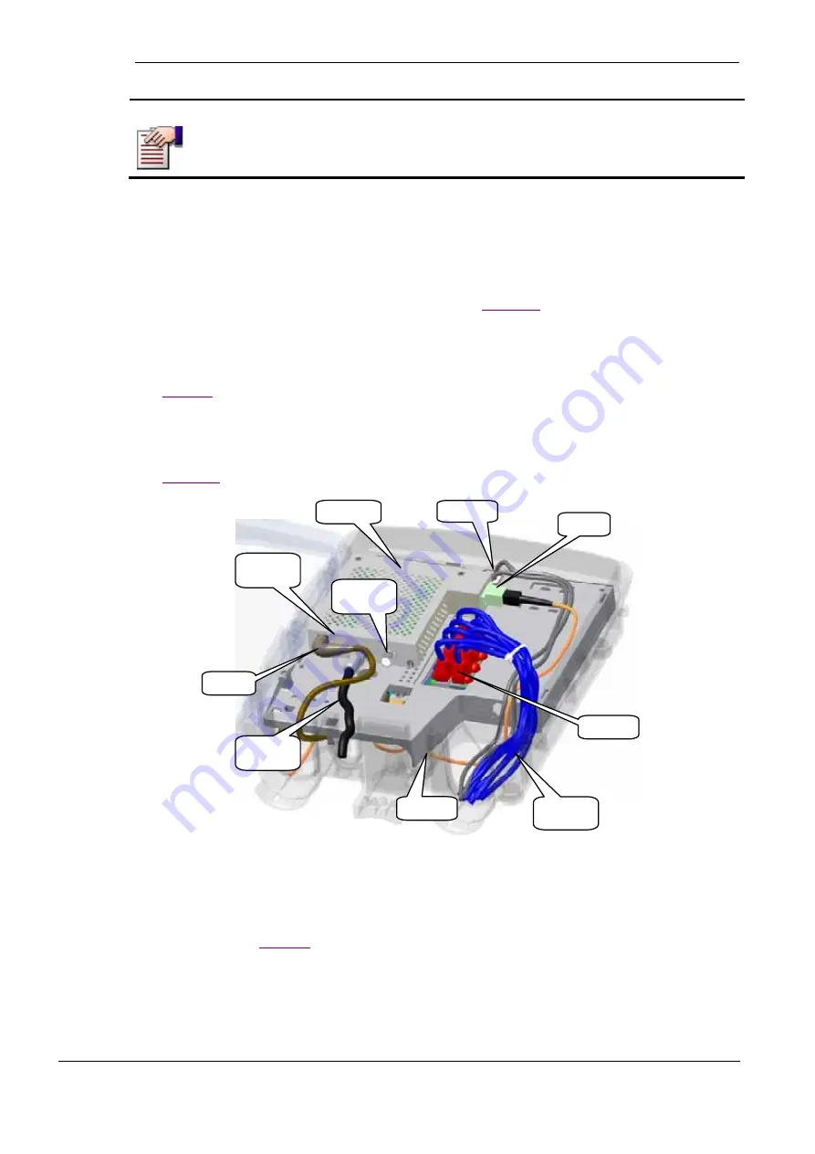
Route a fiber cable from the technician’s area, through the mechanical notch
and connect it to the RF board’s fiber connector (see
Connecting Power to RF Board
1.
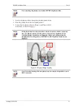
Connect one end of a power cable to the gateway board 12 VDC output (see
2.
Route the cable through the opening located between the bottom of the
gateway board and the cabinet.
3.
Connect the other end of the power cable to the RF board 12 VDC input (see
Connector
12V input
Fiber Input
Connector
2 Telephone
Connectors
8 LAN
Connectors
L-Band RF
Output
Connector
CATV RF
Output
Connector
Video RF
Module
From home
equipment
RF Board Opt
and Power
LEDs
Mechanical
Notch
Figure 12: RF Board Cable Management
Connecting Video to RF Board
1.
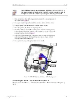
Remove the small black rubber grommet located at the bottom left side of
the cabinet (see
2.
Use a pencil point to punch a small hole in the center of the entrance circle.
3.
Feed the RF video cable (from the subscriber’s home) through the newly
punched grommet hole.
4.
Place the grommet back into its original position.
Installing the GW-483S
21


