background image

GW-483S Installation Guide 

Rev. B 


About This Document 

Who Should Use This Guide 

This guide is intended for network administrators who are proficient with network switching and 
routing concepts. Installation, replacement and maintenance of the equipment described in this 
guide may only be done by trained and qualified service personnel. 

Obtaining Technical Assistance 

Telco Systems provides technical assistance for customers and partners. Users can obtain technical 
assistance by any of the following phone, fax and e-mail options: 

Web Access: 

http://www.telco.com

BATM Advanced Communications – Main Support Center in Israel 

Tel: +972-4-993-5630 
Fax: +972-4-993-7926 
Email: 

support@batm.co.il

Telco Systems a BATM Company – for Americas 

Tel: 1-800-227-0937 (U.S.), 1-781-255-2120 (Outside U.S.) 
Fax: 781-255-2122 
Email: 

techsupport@telco.com

BATM Germany - for Northern Europe 

Tel: +49-241-463-4652 
Fax: +49-241-463-5492 
Email: 

support@batm.de

BATM France – for Southern Europe 

Tel: +33-15-671-2720 
Fax: +33-14-377-1780 
Email : 

support@batm.fr

Telco Systems, a BATM Company Asia Pacific in Singapore 

Tel: +65-6-725-9901 
Fax: +65-6-725-9889 
Email:

 enquiryapac@telco.com

Telco Systems, a BATM Company Asia Pacific in Japan 

Tel: +81-3-5521-1705 
Fax: +81-3-5510-9131 
Email: 

info.jp@telco.com


About This Document 


Summary of Contents for EdgeGate483S

Page 1: ...EdgeGate483S GW 483S Installation Guide MN100167 Rev B ...

Page 2: ...apacity or performance of the mentioned hardware or software products cannot be considered binding but shall be defined in the agreement made between Telco Systems and the customer However Telco Systems has made all reasonable efforts to ensure that the instructions contained in the document are adequate and free of material errors and omissions Telco Systems will if necessary explain issues which...

Page 3: ...his guide are for use by qualified personnel only To avoid shock do not perform any procedures other than those contained in the instructions CAUTION Changes or modifications made to this device that are not expressly approved by the party responsible for compliance could void the user s authority to operate the equipment Safety Considerations 3 ...

Page 4: ...LE GW 483S OPTIONS 8 BEFORE YOU INSTALL 9 INSTALLING THE GW 483S 12 INSTALLING THE CABINET 12 INSTALLING THE VOIP GATEWAY BOARD ENCLOSURE 14 INSTALLING THE RF VIDEO BOARD OPTIONAL 19 DIAGNOSTICS 23 LED FUNCTIONS 23 POST INSTALLATION STATUS 23 DEBUG 23 APPENDIX A CABLE PINOUTS 25 SPECIFICATIONS 27 PHYSICAL SPECIFICATIONS 27 OPERATING CONDITIONS 27 SAFETY AND ELECTROMAGNETIC COMPATIBILITY 27 ACRONYM...

Page 5: ...83S System Telco Cable Management 14 Figure 5 The VoIP Gateway Board Enclosure Top View 15 Figure 6 Gateway Board Connectors 16 Figure 7 A GW 483S System Customer Cable Management 17 Figure 8 A Terminal Bridge Assembly 18 Figure 9 Special Hex Pin Tools 19 Figure 10 RF Video Board Top View 20 Figure 11 RF Video Board Front View 20 Figure 12 RF Board Cable Management 21 Figure 13 Console Cable 24 Ta...

Page 6: ...Web Access http www telco com BATM Advanced Communications Main Support Center in Israel Tel 972 4 993 5630 Fax 972 4 993 7926 Email support batm co il Telco Systems a BATM Company for Americas Tel 1 800 227 0937 U S 1 781 255 2120 Outside U S Fax 781 255 2122 Email techsupport telco com BATM Germany for Northern Europe Tel 49 241 463 4652 Fax 49 241 463 5492 Email support batm de BATM France for ...

Page 7: ...active Ethernet CPE Voice VoIP video data and home networking all in one box Superior voice quality using various QoS mechanisms Supports both 100M and 1G networks in one product Wire speed performance Part of a complete end to end solution Enhanced mechanics and cable management Ports The GW 483S system provides the following ports 100BaseFx and 1GBaseX combo uplink ports SFP 8x10 100BaseTX ports...

Page 8: ...s 2 local phone lines Unpopulated SFP for 100M 1G RF Analog Converter Note A variety of SM MM and bi directional LX SX ZX SFPs is available Accessories need to be ordered separately Model Name Power Option Description GW power 15m Power cable to connect PSU UPS to EdgeGate Length 15m 50ft Outdoor power supply options Model Name Power Option Options GW 483S O M Outdoor powering system including met...

Page 9: ...ing list depends on the ordered GW 483S model but can include some or all of the following items GW 483S Cabinet A VoIP Gateway Board assembly with 2 position Terminal Bridge Two 2 Screw Terminal Bridge assemblies RF Video Converter unit optional as ordered Power Supply kit optional as ordered Console cable Pictures and Drawings The following figures depict different views of the GW 483S system In...

Page 10: ... Button Label Actual location of Reset Button Figure 1 The VoIP Gateway Board NOTE The Power Ready Voice and FO LNK ACT LEDs and the Reset Button are physically located to the left of the Phone 1 Phone 2 connectors but their callout labels have been moved to the right side of the module in order to provide the user with better readability The top to bottom order of the LEDs Reset Button correspond...

Page 11: ...net The Technician Access Area NOTE The console cable is provided for use by service personnel for configuring the EdgeGate 483S VoIP Gateway as described in the EdgeGate VoIP Gateway H 323 MGCP SIP User Guide Document MN100112 NOTE Console Grounding The console cable must be connected to a floating PC i e laptop to prevent the unit from being permanently damaged Introduction 11 ...

Page 12: ...or an outdoor wall The mounting location should have an even surface and should be easily accessible by subscribers or service personnel NOTE The mounting wall must be at 90 degree angle to the ground The cabinet must be situated with all openings facing down NOTE When installing the cabinet outdoors choose a location that is away from down spouts and water sprinklers To install the cabinet 1 Ensu...

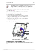
Page 13: ...ity Fiber Splice Routing Tray Telco Grommets Customer Grommets Lower Mounting Ear Cable Shield Cable Shield Upper Mounting Ear Figure 3 A GW 483S System Cable Management Area 3 Feed the service provider s fiber cable through the newly punched grommet hole 4 Place the grommet back into its original position 5 Use the Fiber Routing Tray to store some cable slack see Figure 4 6 Splice the service cab...

Page 14: ...hten the Customer Access screw The cabinet is now connected to the service provider and awaits connection to the subscriber s home Installing the VoIP Gateway Board Enclosure This section describes the installation of the gateway board enclosure and the wiring needed to connect the cabinet to the subscriber s home To install the gateway board enclosure 1 Open the main cabinet cover 2 Hold the encl...

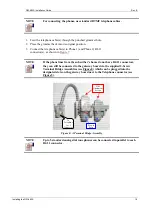
Page 15: ...lignment Slot Terminal Bridge Assembly Holder Figure 5 The VoIP Gateway Board Enclosure Top View Cable Connections This section describes the connection of the wiring needed to connect the cabinet to the subscriber s home Connecting the Internal Fiber Cable to the Gateway Board 1 Open the enclosure to expose the technician s area and to gain access to the gateway board connectors see Figure 6 2 Pl...

Page 16: ...m cable length from the power supply source to the GW 483S cabinet should not exceed 15 meters and should be rated at a minimum of 18 AWG This cable must be ordered separately using the part number shown in the Accessories section Users may build their own cable by using the information provided in Error Reference source not found 2 Remove the large black rubber grommet located at the bottom left ...

Page 17: ...al position 5 Route the cable s underneath the black plastic arm and over the gateway board and then connect the cable s to the LAN RJ 45 connector s on the gateway board as shown in Figure 7 6 Pull on the LAN cable s from outside the cabinet to remove unnecessary cable slack This ensures that the cabinet cover can be closed without exerting undue force on the cover 7 Use a plastic tie wrap to kee...

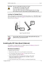
Page 18: ...hone lines from the subscriber s home do not have RJ 11 connectors they can still be connected to the gateway board via the supplied 2 Screw Terminal Bridge Assemblies see Figure 8 which can be plugged into the designated slots on the gateway board next to the Telephone connector see Figure 5 To Telephone 1 or 2 Connector Plug in Posts Wire Attachment Screws Figure 8 A Terminal Bridge Assembly NOT...

Page 19: ...ools NOTE The special Hex Pin Tools are not supplied with the GW 483S but can be purchased at any general hardware store Installing the RF Video Board Optional This installation is optional and thus it can happen anytime after Installing the Cabinet and Installing the VoIP Gateway Board Enclosure Mechanical Installation To install the RF Video board 1 Open the main cabinet cover to expose the gate...

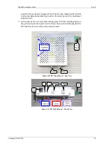
Page 20: ...g pins with their matching holes on the gateway board then press down until you hear a click indicating that the RF board has been secured to the gateway board Fiber Input SC L Band CATV Mechanical Alignment Legs 2 Figure 10 RF Video Board Top View Fiber Input CATV L Band 12 V Input OPT LED PWR LED Mechanical Alignment Legs 2 Mechanical Mating Pins 2 Mechanical Support Posts 2 Figure 11 RF Video B...

Page 21: ...the gateway board and the cabinet 3 Connect the other end of the power cable to the RF board 12 VDC input see Figure 11 Connector 12V input Fiber Input Connector 2 Telephone Connectors 8 LAN Connectors L Band RF Output Connector CATV RF Output Connector Video RF Module From home equipment RF Board Opt and Power LEDs Mechanical Notch Figure 12 RF Board Cable Management Connecting Video to RF Board ...

Page 22: ...nd or the CATV BNC connector as shown in Figure 7 Re locking the Gateway Board After installing the RF board and connecting all the cables listed in the previous section use the procedure in the Locking the Gateway Board section to relock the Gateway board Installing the GW 483S 22 ...

Page 23: ... Activity on the LAN ports One per LAN port Reset Hardware reset button Post Installation Status After successfully Installing the VoIP Gateway Board Enclosure the LEDs will be in the following state Power ON Ready Blinking F O LNK ACT ON NOTE The Voice LED turns ON only after the successful registration of the GW 483S with the SIP or MGCP server If any of the above LEDs shows a different state pr...

Page 24: ...n Guide Rev B NOTE A console cable can be built using the pinouts shown in Table 3 of Appendix A Also shown are the pinouts for building telephone and 10 100BaseT TX Interface cables Figure 13 Console Cable Diagnostics 24 ...

Page 25: ...5 6 Not in use Table 2 10 100BaseT TX Interface Pin to Signal Mapping Pin Signal 1 Rx receive positive 2 Rx receive negative 3 Tx transmit positive 4 Not in use 5 Not in use 6 Tx transmit negative 7 Not in use 8 Not in use Table 3 EdgeGate Console Serial Cable VoIP Gateway Side PC Side RJ 45 Pin DB 9 Female 3 2 6 3 5 5 Appendix A Cable Pinouts 25 ...

Page 26: ...Rev B Table 4 Power Cable Up to 15 m 18 AWG VoIP Gateway Side Power Supply Side Polarity On both ends White is Black is DC Power Plug Center pin diameter 2 1mm Outside Shell diameter 5 5mm Length 9 5mm Appendix A Cable Pinouts 26 ...

Page 27: ...13 F 140 F plus solar load Environmental Humidity 10 90 non condensing UL Listed CSA60950 1 Certification FCC Part 15 Class B IC ES 003 Safety and Electromagnetic Compatibility Safety EN UL 60950 1 CAN CSA C22 2 No 60950 1 03 and IEC 60950 2001 Certification is in process EMC EN 55022 1994 A1 1995 class B EN 300386 V1 3 1 2001 harmonized under EMC directive 89 336 EEC EN55024 CE mark Immunity for ...

Page 28: ...nt in a residential area is likely to cause harmful interference in which case the user will be required to correct the interference at his her own expense Caution Changes or modifications made to this device which are not expressly approved by the party responsible for compliance could void the user s authority to operate the equipment CISPR 22 CLASS B Warning This is a Class A product In a domes...

Page 29: ...CPE Customer Premises Equipment DTMF Dual Tone Multi Frequency FO Fiber Optics FTTH Fiber To The Home MGCP Media Gateway Control Protocol PSU Power Supply Unit REN Ringer Equivalence Number SFP Small form Factor Pluggable SIP Session Initiation Initialization Protocol SOHO Small Office Home Office UPS Uninterruptible Power Supply VoIP Voice over IP Acronyms 29 ...

Page 30: ...y Jun 21 07 Samir Zahra 01 Initial release Aug 06 07 Samir Zahra 02 Updated picture in Figure 7 Nov 14 07 Samir Zahra A Release to Production April 13 08 Bentzi Crystal Olga Menukhin B Updated regarding TUV remarks Updated Obtaining Technical Assistance section Revision History 30 ...

Reviews: