GW-483S Installation Guide
Rev. B
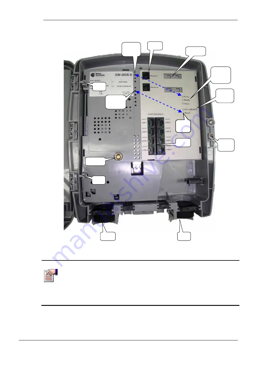
8 LAN
Ports
2 Phone
Lines
Power,
Ready, and
Voice LED
Labels
F.O.
LNK/ACT
LED Label
Phone Line
Adapters
Telco Area
Lock Screw
Cable
Conduit
Cable
Conduit
Customer
Access
Screw
Bottom
Hinge
Top
Hinge
Actual
location of
LEDs
Reset
Button
Label
Actual
location of
Reset Button
Figure 1: The VoIP Gateway Board
NOTE
The Power, Ready, Voice and FO LNK/ACT LEDs and the Reset Button are
physically located to the left of the Phone 1/Phone 2 connectors, but their
callout labels have been moved to the right side of the module in order to
provide the user with better readability.
The top-to-bottom order of the LEDs & Reset Button corresponds to the
top-to-bottom order of their labels.
Introduction
10


