GW-483S Installation Guide
Rev. B
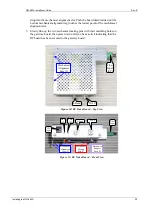
drop into the mechanical alignment slot. Push the board downwards until the
bottom mechanical alignment leg touches the lowest point of the mechanical
alignment slot.
5.
Slowly line-up the two mechanical mating pins with their matching holes on
the gateway board, then press down until you hear a click indicating that the
RF board has been secured to the gateway board.
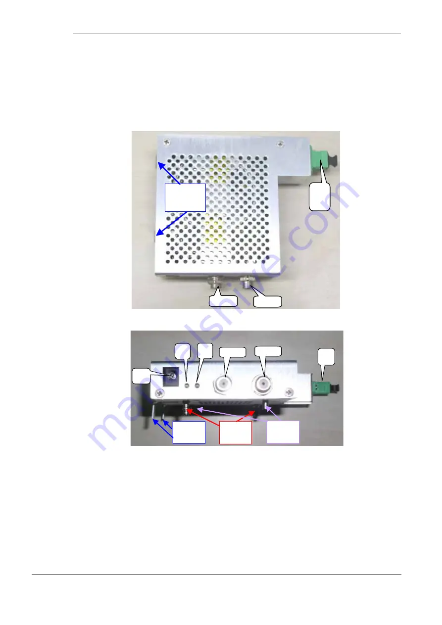
Fiber
Input
(SC)
L-Band
CATV
Mechanical
Alignment
Legs (2)
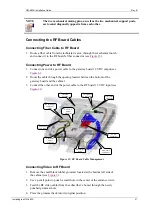
Figure 10: RF Video Board – Top View
Fiber
Input
CATV
L-Band
12 V
Input
OPT
LED
PWR
LED
Mechanical
Alignment
Legs (2)
Mechanical
Mating
Pins (2)
Mechanical
Support
Posts (2)
Figure 11: RF Video Board – Front View
Installing the GW-483S
20


