C O N F I G U R I N G V L A N S V I A T E L N E T
Rev H
187 of 244
22
Configuring VLANs via
Telnet/CLI
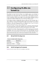
The Virtual Local Area Network (VLAN) acts to logically group a set of stations to
communicate as if they were on the same LAN segment. Traffic between VLANs is
restricted. Unicast and broadcast traffic is forwarded only to LAN segments of the same
VLAN. The Gateway enables you to configure up to eight 802.1Q-compatible VLANs. A
VLAN is identified by a unique number from 1 to 4095 (VLAN ID). By default, the VLAN
configuration is disabled and traffic is free to travel between all Gateway ports.
VLAN tagging is required to identify traffic from more than one VLAN on the same port. A
“tag” is simply the VLAN identification number (VLAN ID), as specified in the 802.1Q
standard. The tag is included in the packets forwarded across the LAN. You can allow
connection to non 802.1Q-compliant devices by adding/removing the tag from packets
according to tag definitions in the VLAN configuration table.
The Gateway is factory set with VLAN ID default value of 1 assigned to all the ports of the
unit. Each port must have a default ID. All packets received on the Gateway ports without a
VLAN tag will inherit the default VLAN ID of the receiving port as their VLAN ID.
To further refine the VLAN configuration and assign a VLAN per protocol, for frames where
the Gateway is the source or the destination, use the Voice and Management Services
Configuration. The user can assign VLAN and priority tags to outgoing frames. This will
help devices such as switches and routers in the LAN to serve the frames with higher priority
queues and with lower delays. Service VLANs can be defined for security reasons also.
22.1
Default VLAN Configuration
Table 21-1 Default VLAN Configuration
Parameter
Default Value
Using VLANs
Disabled
Default ports’ VLAN ID
1, untagged
22.2
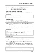
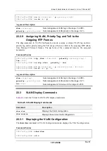
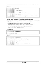
VLAN Configuration Commands
Summary of Contents for AC - 232 - TX
Page 4: ......
Page 24: ......
Page 44: ......
Page 50: ......
Page 68: ......
Page 79: ...C L I C O M M A N D M O D E S Rev H 79 of 244 Figure 9 4 Network Mode show and set Commands ...
Page 81: ...C L I C O M M A N D M O D E S Rev H 81 of 244 Figure 9 8 SIP Mode show and set Commands ...
Page 98: ......
Page 108: ......
Page 156: ......
Page 158: ......
Page 170: ......
Page 184: ......
Page 202: ......
Page 228: ......
Page 234: ......
Page 242: ......

