I N S T A L L A T I O N
Rev H
29 of 244
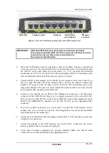
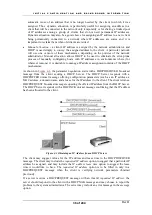
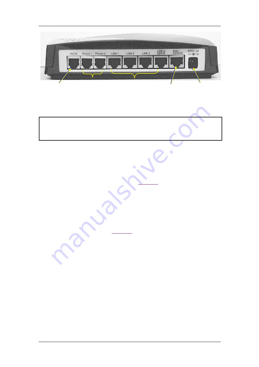
PSTN port
Telephone ports
LAN ports
AUX/Console
port (optional)
DC power
connector
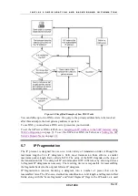
Figure 3-4 AC-232 VoIP Gateway Rear View with AUX/Console Port
IMPORTANT
ONLY the PSTN (Life Line) port can be connected to the Public
Telecommunication Network. The Phone ports are intended for indoor
connections only and may not be connected to the
Telecommunication Network.
2.
Place the VoIP Gateway unit on a desktop or other level surface. Choose a location that
is near the devices to be connected and close to an electrical outlet. You may also mount
the GW-232 on the wall, using two wood screws 6.1” (15.5 cm) apart for horizontal
positioning or 2.68” (6.8 cm) apart for vertical positioning. Holes for mounting on the
wall are situated at the bottom of the unit (see
3.
Connect the DC power adapter cord to the DC power connector at the rear of the 232 or
282 unit. Plug the other end of the adapter power cord into the adapter. Connect the
adapter’s AC plug into the AC power source. Fasten the DC power-feed cable to the
clasp at the bottom of the unit to avoid accidental disconnection. Be sure to use only the
power adaptor that was delivered with the unit.
4.
Connect to the network via an RJ-45 LAN 100Base-TX connector or the fiber optic
connector of the GW-282 unit (
) or copper connector of the Access282 (AC-
282) unit. For the GW-232-TX, connect the LAN/WAN to the LAN4 uplink port via an
RJ-45 LAN 100BASE-TX connector. For the GW-232-FX, use the appropriate fiber
connector.
5.
If you use an RJ-45 connector, use a cross cable to connect the VoIP Gateway unit to
another unit, or to a switch or hub. The cable length must not exceed the maximum
length specified for the media type.
6.
Connect any required PC to the unit using a straight cable. For 232 products you can use
straight or a crossed cable.
7.
Connect the phones to the VoIP Gateway unit via the RJ-11 connectors. Up to five
phones in parallel may be connected to each port.
8.
Verify that all system components are properly installed. Make sure that all cable
connectors are securely positioned in the appropriate ports.
Summary of Contents for AC - 232 - TX
Page 4: ......
Page 24: ......
Page 44: ......
Page 50: ......
Page 68: ......
Page 79: ...C L I C O M M A N D M O D E S Rev H 79 of 244 Figure 9 4 Network Mode show and set Commands ...
Page 81: ...C L I C O M M A N D M O D E S Rev H 81 of 244 Figure 9 8 SIP Mode show and set Commands ...
Page 98: ......
Page 108: ......
Page 156: ......
Page 158: ......
Page 170: ......
Page 184: ......
Page 202: ......
Page 228: ......
Page 234: ......
Page 242: ......

