background image

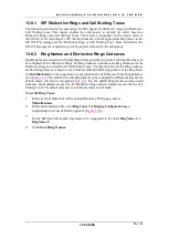
M I S C E L L A N E O U S   C O N F I G U R A T I O N   V I A   T H E   W E B  

Rev H 

124 of 244 


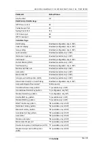
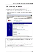
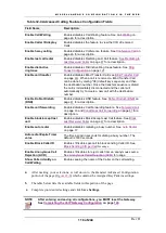
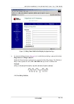
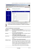
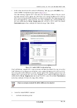
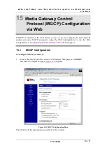
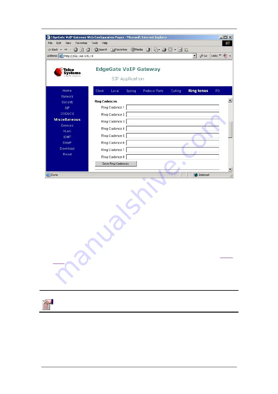
Figure 12-9 

Ring Cadence Fields in the Ringing 

Configuration Page 

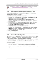
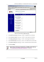
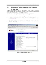
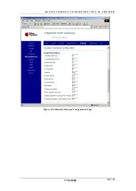
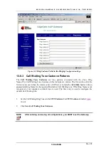
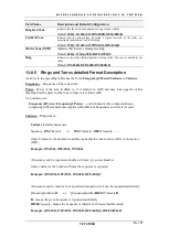
13.8.3   Call Waiting Tone Cadence Patterns 

The 

Call Waiting  Tone Cadences

  are tone patterns associated with the above Ring 

Names.The Call Waiting Tone Cadences table includes six entries. The five entries after the 
first entry are used when the remote caller or SIP server include the 

Alert-Info

 header with an 

appropriate Ring Name for the required Distinctive Call Waiting tone. If the Ring Name is not 
recognized or not supplied, a default tone is used. The first entry is used to configure the 
default Call Waiting tone. 


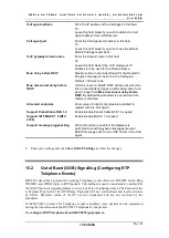
1. 

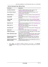
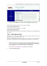
Set the Call Waiting Ring Tones in the 

CWT Cadence 1

 to 

CWT Cadence 6

 fields (

Figure 

12-10

)

2. 

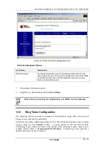
Click 

Save Call Waiting Tone Cadences


NOTE 


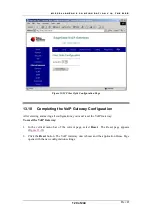
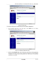
After entering and saving all configurations, you MUST reset the Gateway. 


Summary of Contents for AC - 232 - TX

Page 1: ...Rev H EDGEGATE ACCESS VOIP Gateway A C 2 3 2 T X G W 2 3 2 S F P G W 2 8 2 G W 2 8 2 S A C 2 8 2 G W 4 8 2 S G W 4 8 3 S G W 4 8 3 D H 3 2 3 MGC P SIP USER GUIDE ...

Page 2: ... 2004 Adapted for Version 4 12 D December 2005 Adapted for Version 4 57 E May 2006 Added GW 232 Adapted for Version 5 5 F June 2007 Added GW 483S Adapted for Version 5 8 G May 2009 Added GW 483D Adapted for Version 5 10 H December 2009 Adapted for Version 5 11 ...

Page 3: ...ems and the customer shall bind and obligate Telco Systems Telco Systems however has made all reasonable efforts to ensure that the instructions contained in this document are adequate and free of material errors and omissions Telco Systems will if necessary explain issues which may not be covered by the document Telco Systems sole and exclusive liability for any errors in the document is limited ...

Page 4: ......

Page 5: ...tion is provided below Web Access http www telco com Email support telco com BATM Advanced Communications Main Support Center in Israel Tel 972 4 993 5630 Fax 972 4 993 7926 Telco Systems A BATM Company for the Americas Tel 1 800 227 0937 U S 1 781 255 2120 Outside U S Fax 1 781 255 2122 Telco Systems A BATM Company for Northern Europe Tel 49 241 463 5490 Fax 49 241 463 5491 Telco Systems A BATM C...

Page 6: ...lan Syntax 33 5 1 3 Dial Plan Examples 34 5 2 UNDERSTANDING DHCP 35 5 2 1 When Should Clients Use DHCP 37 5 3 UNDERSTANDING NAT AND NAPT 37 5 4 UNDERSTANDING NTP 37 5 4 1 Daylight Saving Time Summer Time 38 5 5 UNDERSTANDING SYSLOG 38 5 5 1 Remote Logging 39 DNS RESOLVER 39 5 7 IP FRAGMENTATION 40 6 INITIAL SETUP 42 6 1 KEYPAD CONFIGURATION ENABLED ONLY ON 232 GATEWAY PRODUCTS 43 6 1 1 Keypad Conf...

Page 7: ...g the TFTP Server Root Configuration File via Telnet 63 8 6 CREATING AND ENCRYPTING CONFIGURATION FILES 64 9 CONFIGURING THE VOIP GATEWAY VIA TELNET OR CLI CONSOLE 65 9 1 STARTING A TELNET SESSION 65 9 2 ACCESSING THE CLI 65 10 CLI COMMAND MODES 69 10 1 COMMAND MODES 69 10 1 1 Enable Mode 69 10 1 2 Commands Mode 69 10 1 3 Report Mode 69 10 1 4 Statistics Mode 70 10 1 5 Download Mode 70 10 1 6 Conf...

Page 8: ...IBER OPTIC CONFIGURATION 128 13 10 COMPLETING THE VOIP GATEWAY CONFIGURATION 129 14 PROTOCOL H 323 CONFIGURATION VIA WEB 131 14 1 DEFAULT H 323 CONFIGURATION 131 14 2 SETTING THE H 323 CONFIGURATION 131 14 2 1 H323 Gatekeeper Settings 132 14 2 2 Gateway Settings 132 14 3 DTMF SIGNALING 133 14 4 AUDIO CODEC CONFIGURATION 134 14 4 1 Default Audio CODEC Configuration Settings 134 15 MEDIA GATEWAY CON...

Page 9: ...f the LAN Interface 178 20 SECURITY CONFIGURATION VIA TELNET CLI 179 20 1 DEFAULT SECURITY CONFIGURATION 179 20 2 SECURITY CONFIGURATION COMMANDS 179 20 2 1 Accessing LAN Configuration Mode 180 20 2 2 Enabling Advanced Security 180 20 2 3 Enabling DHCP Security 180 20 2 4 Setting Management IP Addresses 181 20 3 SECURITY DISPLAYING COMMANDS 181 20 3 1 Displaying All Security Parameters 182 20 3 2 ...

Page 10: ... 199 24 2 4 Enabling Flow Control on the Interface 200 24 3 INTERFACE DISPLAYING COMMANDS 200 24 3 1 Displaying the Specified Interface Configuration 200 24 3 2 Displaying the Configuration of all the Interfaces 201 25 EXECUTING REPORTS VIA TELNET CLI 203 25 1 REPORT COMMANDS 203 25 1 1 Accessing Report Mode 203 25 1 2 Accessing Statistics Mode 203 25 1 3 Displaying Interface Statistics 204 25 1 4...

Page 11: ...9 Displaying the Password for Line 2 225 26 3 20 Displaying the NAT IP Address 226 26 3 21 Displaying the RTP RTCP Port Base 226 26 3 22 Displaying the STUN Server IP Address 226 26 3 23 Displaying the STUN Server s Port Number 227 26 3 24 Displaying the Phone Line Status 227 26 3 25 Displaying the Phone Line Status for Pulse Metering 227 27 MGCP CONFIGURATION VIA TELNET CLI 229 27 1 DEFAULT MGCP ...

Page 12: ...Number of Line 2 240 28 3 6 Displaying the Caller ID for Line 1 240 28 3 7 Displaying the Caller ID for Line 2 240 29 COMPLETING THE GATEWAY CONFIGURATION VIA TELNET CLI 243 29 1 GENERAL COMMANDS 243 29 1 1 Accessing Commands Mode 243 29 1 2 Rebooting the Gateway 243 29 1 3 Setting the Configuration to the Factory Defaults 244 29 1 4 Downloading Image or Configuration File Using TFTP HTTP 244 ...

Page 13: ...der Screen 53 Figure 7 2 HTTP Download Page 57 Figure 7 3 Network Status Page 60 Figure 7 4 Network Update Page 60 Figure 7 5 Automatic Configuration Page 61 Figure 9 1 CLI Command Tree 76 Figure 9 2 Interface Mode show and set Commands 78 Figure 9 3 Security Mode show and set Commands 78 Figure 9 4 Network Mode show and set Commands 79 Figure 9 5 SNMP Mode show and set Commands 80 Figure 9 6 VLAN...

Page 14: ...dset Advanced Configuration Page 119 Figure 12 7 Dead air Period Configuration Field 121 Figure 12 8 Ring Name Fields in the Ringing Configuration Page 123 Figure 12 9 Ring Cadence Fields in the Ringing Configuration Page 124 Figure 12 10 Call Waiting Tone Cadence Fields in the Ringing Configuration Page 125 Figure 12 11 Call Progress Tones Fields in the Ringing Configuration Page 126 Figure 12 12...

Page 15: ...able 12 3 Clock Localization Configuration Fields 112 Table 12 4 Advanced Calling Features Configuration Fields 118 Table 12 5 Assigned Key Patterns Fields 120 Table 12 6 Dead Air Period 121 Table 12 7 Call Progress Tones Descriptions 126 Table 13 1 Default H 323 Configuration 131 Table 13 2 Voice and Management Services Configuration Fields 134 Table 17 1 RSTP Port Role Assignments 159 Table 18 1...

Page 16: ... Table 24 1 Report Commands 203 Table 24 2 Interface Statistics Parameters 206 Table 25 1 Default SIP Configuration 210 Table 25 2 SIP Configuration Commands 210 Table 25 3 SIP Display Commands 219 Table 26 1 Default MGCP Configuration 229 Table 26 2 MGCP Configuration Commands 229 Table 26 3 MGCP Display Commands 231 Table 27 1 Default H 323 Configuration 235 Table 27 2 H 323 Configuration Comman...

Page 17: ...ptic uplink port a rugged weatherproof version used outdoors and offered with different power options All EdgeGate 482S GW 482S One fast or gigabit fiber optic uplink port a rugged weatherproof scaled down version of GW 282S used outdoors and offered with different power options All EdgeGate 483S GW 483S One fast or gigabit fiber optic uplink port a rugged weatherproof scaled down version of GW 48...

Page 18: ...ion of the products covered in this manual are similar the products will be referred to generically in this manual as the VoIP Gateway rather than by individual product name Any differences between products will be clearly noted This chapter includes an overview of these products and information for obtaining technical assistance The following chapters include brief installation instructions and f...

Page 19: ...it Ethernet uplink are also available for wide bandwidth applications The EdgeGate VoIP Gateway 282S 482S 483S 483D products are rugged weather proof systems for outdoors installations The Edgegate 482S is a scaled down lower cost version of the Edgegate 282S Figure 1 1 EdgeGate VoIP Gateway GW 282 Access AC 282 Front View Figure 1 2 GW 282S Front View ...

Page 20: ...O V E R V I E W Rev H 20 of 244 Figure 1 3 GW 482S Front View Figure 1 4 GW 232 Front View Figure 1 5 GW 483S Front View Open Door Figure 1 6 GW 483D Front View Open Door ...

Page 21: ... or G 723 1 or G729A B or G726 Full duplex acoustic echo cancellation with an effective 64ms tail length 18dB network echo cancellation Comfort noise generation and voice activity detection 10 100 mili seconds packetization Fixed and Adaptive Jitter buffer Fax Modem Tone Detection DTMF tone generation and detection Data Communications Feature Notes Call tone generation Caller ID generation On hook...

Page 22: ... 802 1Q compatible tagged VLANs VLAN support for voice channel Layer 3 Feature Notes Supports assigning priority to voice frames with the 802 1 Priority tag or TOS field Advanced error and packet loss concealment technology Support of IGMP v2 Snooping with fast leave DHCP compliant IP address selection or fixed IP selection Support of IP fragmentation Device Management Feature Notes Embedded HTTP ...

Page 23: ...in this guide are under Class 1 emission levels according to IEC 60825 1 and the FDA 21 CFR 1040 10 and 1040 1 These products shall not be installed in an optical network handling above Class 1 levels 2 3 How to Get Help For technical support please contact your local distributor who supplied the unit ...

Page 24: ......

Page 25: ...rial port LAN cables to connect the VoIP Gateway PC s and your local network Use a cross cable for the Ethernet connections from the VoIP Gateway to another one or to a switch or hub Use a straight cable to connect the unit to computer devices Use a VoIP Gateway console cable to connect your PC serial port to the AUX Console port on the VoIP Gateway The call management devices and applications app...

Page 26: ...P R E I N S T A L L A T I O N R E Q U I R E M E N T S Rev H 26 of 244 NOTE Pulse dial telephones and accessories are not supported ...

Page 27: ...he Telecommunication Network 4 1 Installing the EdgeGate To install your indoor VoIP Gateway unit 1 Unpack the EdgeGate unit Figure 3 1 shows the connectors on the rear of the AC 282 copper port and GW 282 fiber optic port Figure 3 2 Figure 3 3 and Figure 3 4 show the GW 232 ports The AC 282 provides a copper cable connector The GW 232 and GW 282 provide a fiber optic connector The RJ 11 telephone...

Page 28: ...iber Link Activity connector LEDs or copper port AC 282 Figure 3 1 GW 282 AC 282 VoIP Gateway Back Panel with AUX Console Port PSTN port Telephone ports LAN ports SFP 100BaseFX Uplink port DC power connector Figure 3 2 GW 232 SFP VoIP Gateway Rear View PSTN port Telephone ports LAN ports DC power connector Figure 3 3 AC 232 VoIP Gateway Rear View ...

Page 29: ...apter Connect the adapter s AC plug into the AC power source Fasten the DC power feed cable to the clasp at the bottom of the unit to avoid accidental disconnection Be sure to use only the power adaptor that was delivered with the unit 4 Connect to the network via an RJ 45 LAN 100Base TX connector or the fiber optic connector of the GW 282 unit Figure 3 1 or copper connector of the Access282 AC 28...

Page 30: ...4 on page 20 They indicate Link and Activity status for each of the LAN connections A steady glow indicates Link and a blinking LED indicates Activity 4 3 Status LEDs Status LEDs are located on both the front and rear of the EdgeGate GW 282 and Access AC 282 units Figure 1 1 on page 19 and on the front of the GW 232 Figure 1 4 on page 20 They provide useful operating information for H 323 MGCP SIP...

Page 31: ... F Humidity 95 non condensing DC adapter input power 100 250V 47 63Hz EdgeGate input power 12 VDC Power Consumption 16W Maximum configuration 8W Minimum configuration Table 3 4 EdgeGate VoIP Gateway 232 GW 232 Dimensions 4 72 W x 7 36 L x 1 77 H 120 W x 187 L x 45 H mm Weight 1 32 lbs 0 6 kg with DC power adapter Operating temperature 0 C 45 C 32 F 113 F Humidity 95 non condensing DC adapter input...

Page 32: ...lace battery the replace battery alarm is designed as an early warning signal It indicates that the battery has failed its periodic test Replace the battery is required 3 Battery missing the alarm indicates that the battery is disconnected Load will not be supported if the utility power fails 4 Low battery low battery alarm warns of a low battery condition It indicates that the battery has been re...

Page 33: ...al plan when using the H 323 protocol via the Web see Gateway Settings on page 132 To set the dial plan when using the H 323 protocol via Telnet see Setting the Dial Plan Matching String on page 212 To set the dial plan when using the SIP protocol via the Web see Default SIP Configuration SIP Extensions Line Configuration on page 143 You can configure a Dial Plan of up to 254 characters in the Dia...

Page 34: ...a match is produced if you dial zero followed by a four second delay or if you dial any seven digit number 5 1 3 2 Basic Dial Plan Example The basic dial plan allows dialing of any number of digits The dial plan is x T This ensures a match against one or more digits A match is produced when a delay of about 4 seconds follows any number of dialed digits 5 1 3 3 Complex Dial Plan Example The followi...

Page 35: ...8 5 2 Understanding DHCP Dynamic Host Configuration Protocol DHCP provides a framework for passing configuration information to hosts on a TCP IP network DHCP based on the Bootstrap Protocol BOOTP adds the capability of automatic allocation of reusable network addresses and additional configuration options DHCP captures the behavior of BOOTP relay agents and DHCP participants can interoperate with...

Page 36: ...gnment outside of the DHCP mechanisms As shown in Figure 4 1 the parameter negotiation starts with a DHCPDISCOVER broadcast message from the client seeking a DHCP Server The DHCP Server responds with a DHCPOFFER unicast message offering configuration parameters such as an IP address a MAC address a domain name and a lease for the IP address to the client The client returns a DHCPREQUEST broadcast ...

Page 37: ...o the other network designated as outside The translation operates in conjunction with routing so that NAT can simply be enabled on a customer side Internet access router when translation is desired Network Port Address Translator NAPT maps a single public address to one or many internal addresses and all network IP addresses on the connected computers are local and cannot be seen by the outside w...

Page 38: ... start and end dates and times and whether or not the time adjustment recurs every year For enabling automatically adjust the internal clock to daylight saving time according to the local time zone via Web see Clock Localization on page 111 5 5 Understanding Syslog The system message logging can save messages in a Syslog server The system message logging facility Provides you with logging informat...

Page 39: ...mnemonic handle to an Internet address Because it would be impractical to maintain a central list of domain name IP address correspondences the lists of domain names and IP addresses are distributed throughout the Internet in a hierarchy of authority There is probably a DNS server within close geographic proximity to your access provider that maps the domain names in your Internet requests or forw...

Page 40: ... IP Fragmentation The IP protocol is designed for use on a wide variety of transmission links Although the maximum length of an IP datagram is 64K most transmission links enforce a smaller maximum packet length limit called a MTU The value of the MTU depends on the type of the transmission link The design of IP accommodates MTU differences by allowing devices to fragment IP datagrams as necessary ...

Page 41: ...O U N D I N F O R M A T I O N Rev H 41 of 244 for IP fragmentation and reassembly For more information about the mechanics of IP fragmentation and reassembly please see RFC 791 The GW 232 282 482 483S 483D models have a limitation to process up to 5 fragments ...

Page 42: ...n GW 483S and GW 483D 3 Optionally configure and save other general parameters 4 Reset the Gateway You can use a terminal to configure local basic settings such as the unit s IP and most of the unit s parameters A convenient way to set up the Gateway configuration is to download the configuration file to the Gateway see Chapter 7 Upgrading the Gateway Firmware and Downloading Configuration Files F...

Page 43: ...l will glow a steady green and after about 30 seconds the unit will power up with factory defaults To set the IP mode To change the IP mode from DHCP to fixed or vice versa dial 3427937 D H C P Y E S for DHCP or 342766 D H C P N O for fixed IP 10 1 0 54 Mask 255 255 0 0 The Management LED on the front panel will glow a steady green for about 3 seconds and the unit will boot with the required IP se...

Page 44: ......

Page 45: ... all equipment is powered up 2 Check that the Call Server is running and that all endpoints are registered 3 Check for a dial tone on each of the VoIP Gateway unit endpoints phone lines registered by the Call Server A dial tone is not present until the VoIP Gateway unit is addressed and powered up the Call Server is running and the endpoint phone line is registered Keypad Configuration will be act...

Page 46: ...ings or after the new callee answers put the handset down Before the new callee picks up the handset the phone will ring both at the destination number and at your line By picking up the handset the callee at the destination number will be engaged in the call with the original caller Your phone will stop ringing If the callee at the destination number does not pick up the handset you can receive t...

Page 47: ...y hangs up and the caller does not pick up the phone when the special ring tone is heard then on the next attempt to use the phone the Caller will get a busy signal indicating that the Auto Redial service succeeded To place the next call the caller needs to hang up and pick up the phone again To cancel the periodic Auto Redialing before the timeout has been reached dial 86 7 4 12 Block Sending CID...

Page 48: ...d party s number Once the third party answers the call a 3 way call is established To drop the conference dial flash 8 7 5 3 Forward a Call To set the Forward option dial 2 destination number All calls to the phone with Forward set will be received at the destination number To cancel the Forward option dial 3 7 5 4 Transfer Call To transfer a call that you are receiving to another number dial flas...

Page 49: ...H E E D G E G A T E V O I P G A T E W A Y U N I T Rev H 49 of 244 7 6 Advanced Calling Features for MGCP Advanced calling features are supported Refer to your Call Agent for the advanced calling features supported ...

Page 50: ......

Page 51: ...y using a DHCP server that is based at the provider s network The TFTP HTTP server IP address and the file name are provided by the DHCP server during the Bootp process and at half lease time You can set DHCP server Automatic Configuration either via the Web see Setting DHCP Automatic Configuration via the Web on page 60 or via Telnet see Setting DHCP Automatic Configuration via Telnet on page 61 ...

Page 52: ...mware file names Firmware file NOTE If the Firmware file versions APP_VERSION LDR_VERSION parameters are used a firmware upgrade will take place only if the Firmware file version is different from the current firmware version The name of the root configuration file must be of the format ipg_xxxx cfg Configuration files must include header Configuration Parameters Don t edit this line You will find...

Page 53: ... server to the directory where the filename is located 2 On your VoIP Gateway Web interface click Download in the vertical menu at the left of the screen The Download page appears as shown below This figure shows the Server address and filename already entered 3 At the Download page enter the Server address and the filename of the Downloader Code version The filename must be in the correct format ...

Page 54: ...vertical menu See the figure below The Downloader Code Version should now be the updated code version 7 Notice in the screen capture above that there is no Application Code loaded Now you must download the Application Code Click Download in the vertical menu 8 Enter the Server address and Filename In the example screen below the H 323 code will be loaded ...

Page 55: ... O N F I G U R A T I O N F I L E S Rev H 55 of 244 9 Click Start Download 10 The Download Successful screen appears Then the Loader Home screen appears indicating the new Application Code version 11 Click Reset in the vertical menu You are now in the new Application in this case H 323 ...

Page 56: ... Downloading Code Versions over the Web via the HTTP Server Follow these steps to download Downloader Code and Application Code to the VoIP Gateway using the HTTP server at the Web interface 1 At your VoIP Gateway Web interface click Download in the vertical menu at the left of the screen The Download page appears as shown in Figure 7 2 ...

Page 57: ...Click Browse in the HTTP Download method section and locate the directory where the Downloader Code filename is stored Note that the filename must be in the correct format upgr_xxx_y rom xxx is the product number e g 282 482 483 y is the software version number e g 4_57_49 3 Click Start HTTP Download 4 At the end of a successful download the following screen appears ...

Page 58: ...tice in the screen capture above that there is no Application Code loaded Now you must download the Application Code Click Download in the vertical menu 11 Click Browse in the HTTP Download method section of the page and locate the directory where the Application Code filename e g h323_282_4_57_49 rom is stored 11 Click Start HTTP Download 12 The Download Successful screen appears Then the Loader ...

Page 59: ... I N G T H E G A T E W A Y F I R M W A R E A N D D O W N L O A D I N G C O N F I G U R A T I O N F I L E S Rev H 59 of 244 12 Click Reset in the vertical menu You are now in the new Application in this case H 323 ...

Page 60: ...eries the DHCP server for an IP address and a boot file during boot and at half lease time 8 4 1 Setting DHCP Automatic Configuration via the Web 1 Open the Network page Figure 7 3 Figure 7 3 Network Status Page 2 In the horizontal menu bar of the Network page select Network Update Figure 7 4 Verify that the Use DHCP to obtain LAN configuration option is selected Figure 7 4 Network Update Page 3 I...

Page 61: ...der is being used for DHCP options o Option 67 Bootfile Name Option used to identify a boot file the root file when the file field is the DHCP header that is being used for DHCP options Set the Automatic configuration ID Set the Automatic configuration ID to be different from the value on the DHCP Server The Automatic configuration ID on the DHCP Server can be set to the value always which causes ...

Page 62: ...nfiguration mode IPG Config Network set options6667 y IPG Config Network show options6667 IPG Config Network IPG Config Network options6667 o y Set the Automatic configuration ID to a value different from the value on the DHCP server by using the set id se id command in Network Configuration mode You can display the Automatic configuration ID by using the show id sh id command in Network Configura...

Page 63: ... HTTP or TFTP in the Server protocol field 5 Set the server IP address for the location of the configuration files in the Server Address field 6 Set the name of the root configuration file in the File name field The file name has the following syntax ipg_xxxx cfg where xxxx is free text up to 97 characters in length 7 Set the polling time in hours in the Polling time hours field The polling time s...

Page 64: ...the root configuration file The file name has the following syntax ipg_xxxx cfg where xxxx is free text IPG Config Network set file ipg_test cfg IPG Config Network show file IPG Config Network IPG Config Network file f ipg_test cfg 5 Reboot the Gateway to effect the changes by using the reboot power r p command in Commands mode IPG Commands reboot power IPG Commands Warning Reset system y n y 8 6 ...

Page 65: ... set up the IP parameters as described in Accessing the CLI below or in Assigning an IP Address to the VoIP Gateway using Web Configuration on page 83 To open the Telnet session you must specify the IP address of the VoIP Gateway that you want to manage Check the user manual supplied with your Telnet facility if you are unsure of how to do this Once the connection is established you will be prompt...

Page 66: ...rity and no flow control Once the initialization process ends proceed as follows 4 Press Enter You are prompted for a password 5 If a password has been entered in the Set Security Administrator Password Page see Figure 11 1 on page 100 enter this password Otherwise Press Enter to invoke the opening screen The opening screen includes specifications of Software versions Unit s current IP settings Un...

Page 67: ...bing each command briefly and showing the minimal abbreviation allowed for each command name To apply a CLI command 1 Type the command in lowercase characters You may abbreviate any or all of the keywords Examples of abbreviations l or for list en for end as a rule you may abbreviate keywords down to the shortest unique abbreviation any length between the full and the shortest unique presentation ...

Page 68: ......

Page 69: ...see Setting the Password on page 99 10 1 2 Commands Mode The Commands mode allows you to perform general operations on the Gateway such as rebooting restoring the Gateway to the factory defaults and downloading a configuration file or software image The Commands mode is indicated by the following prompt IGP Commands To access the Commands mode Type the commands command or the c shortcut in Enable ...

Page 70: ...nds with the Report prompt IGP Report Step 2 Type the statistics command or the s shortcut in Report mode IGP Report statistics IGP Report s The system responds with the Statistics prompt IGP Report Statistics 10 1 5 Download Mode The Download mode allows you to display the configuration download status The Download mode is indicated by the following prompt IGP Report Download To access the Downlo...

Page 71: ...es that the CLI is in Interface Configuration mode IGP Config Interface To access the Global Configuration mode Type the config command or the con shortcut in Enable mode IGP config IGP con The system responds with the Global Configuration prompt IGP Config Interface Table 9 1 shows the configuration modes available in the Gateway Table 9 1 Configuration Modes Summary Configuration Mode For config...

Page 72: ...AN Virtual LANs VLANs settings IPG Config vlan IPG Config VLAN IPG Config v IPG Config VLAN HTTP HTTP Hypertext Transfer Protocol settings IPG Config http IPG Config HTTP IPG Config ht IPG Config HTTP SIP SIP Session Initiation Protocol settings IPG Config sip IPG Config SIP IPG Config si IPG Config SIP H 323 H 323 protocol settings IPG Config h323 IPG Config H323 IPG Config h3 IPG Config H323 MGC...

Page 73: ... Allows you access to commands you can perform with the Gateway reboot to reboot the unit default to set factory defaults copy to update unit s image send to display RTP statistics or to backup unit s configuration ping to ping a network device from in the VoIP Gateway config Accesses Config mode allowing you to configure basic VoIP Gateway parameters debug Accesses command to set or stop the igmp...

Page 74: ...d you can view the IP address that was assigned to the unit by the DHCP server The current IP can also be viewed in the System Information display invoked from the main mode by the CLI show command snmp Accesses snmp mode This mode includes commands to set SNMP communities You can find a description of the SNMP options as accessed via the Web in section 10 7 vlan Accesses vlan mode VLAN configurat...

Page 75: ...fig security se Advanced Security Configuration IPG Config netconfig n Network Configuration IPG Config snmp sn SNMP Configuration IPG Config vlan v VLAN Configuration IPG Config http ht HTTP Configuration IPG Config mgcp mg MGCP Configuration IPG Config rstp r RSTP Configuration IPG Config sip si SIP Configuration IPG Config mac ma MAC Address Table IPG Config igmp ig IGMP Configuration IPG Confi...

Page 76: ...sents a schematic map of the CLI command tree The diagram is correct at the time of writing this document and should not be regarded as an ultimate reference Figure 9 1 CLI Command Tree In the diagram mode names are enclosed in rectangles The help list end exit and quit commands are available at all modes as indicated by the broken lines that lead from each mode to these commands ...

Page 77: ...show and set commands varies for the different configuration modes Expanded schemes of these commands are presented in the figures that follow The CLI commands are described in the following sections The following figures show the structure of the show and set commands in the various configuration modes The diagrams are correct at the time of writing this document and should not be regarded as an ...

Page 78: ...C L I C O M M A N D M O D E S Rev H 78 of 244 Figure 9 2 Interface Mode show and set Commands Figure 9 3 Security Mode show and set Commands ...

Page 79: ...C L I C O M M A N D M O D E S Rev H 79 of 244 Figure 9 4 Network Mode show and set Commands ...

Page 80: ...C L I C O M M A N D M O D E S Rev H 80 of 244 Figure 9 5 SNMP Mode show and set Commands Figure 9 6 VLAN Mode show and set Commands Figure 9 7 H323 Mode show and set Commands ...

Page 81: ...C L I C O M M A N D M O D E S Rev H 81 of 244 Figure 9 8 SIP Mode show and set Commands ...

Page 82: ...C L I C O M M A N D M O D E S Rev H 82 of 244 Figure 9 9 MGCP Mode show and set Commands Figure 9 10 HTTP Mode show and set Commands Figure 9 11 Power Mode show and set Commands ...

Page 83: ...e button at the bottom of the page Once all settings have been saved select the Reset option on the left hand side of the Web page to reset the VoIP Gateway and activate the new settings 11 1 Assigning an IP Address to the VoIP Gateway using Web Configuration To change the mode from using DHCP to fixed IP or to assign a different fixed IP address configure the unit as follows 1 If the VoIP Gateway...

Page 84: ... O N F I G U R I N G T H E V O I P G A T E W A Y V I A T H E W E B Rev H 84 of 244 Figure 10 1 VoIP Gateway Home Page 4 In the vertical menu bar on the left click Network The Network Status Page appears ...

Page 85: ...N G T H E V O I P G A T E W A Y V I A T H E W E B Rev H 85 of 244 Figure 10 2 Network Status Page 5 To change network settings select Network Update on the horizontal menu bar The Network Update page appears Figure 10 3 ...

Page 86: ...ate Page 6 Select either of the following options To use a fixed IP address Select fixed LAN Configuration Fill in or change the fields associated with fixed IP addressing IP Address IP Netmask IP Gateway IP DNS Server Host Name Domain Name Or To use a DHCP server Select Use DHCP to obtain LAN configuration ...

Page 87: ... to your VoIP Gateway see the IP address in the CLI opening screen that appears when the unit boots with a terminal see Upgrading the Gateway Firmware and Downloading Configuration Files on page 51 11 1 2 Using VoIP Gateway with a Fixed Address If you do not have access to a DHCP server and your Gateway is configured to use a DHCP server or if you do not know the IP address used by the Gateway con...

Page 88: ...Auto Configuration the ID can also be set in the root Configuration file The ID at the DHCP server or in the Configuration file can be set to the literal value always causing the configuration file to be executed on every boot without comparing to the ID stored in the Gateway 4 In DHCP download Bootp the Gateway must be in DHCP mode The name of the root configuration file and the IP of the TFTP se...

Page 89: ...ion file and will determine if an upgrade is needed 7 Set the Server IP address 8 Set the file name root configuration file to download 9 Set the Server protocol HTTP or TFTP 11 4 VLAN Configuration To set VLAN configuration on the VoIP Gateway unit 1 In the vertical menu bar of the current VoIP Gateway Web page select VLAN The VLAN Configuration page appears Figure 10 5 NOTE The 282 482 product s...

Page 90: ... same LAN segment Traffic between VLANs is restricted Unicast and broadcast traffic is forwarded only to LAN segments of the same VLAN The VoIP Gateway enables you to configure up to sixteen 802 1Q compatible VLANs on the 282 482 483S 483D model and up to 8 VLANs on the 232 nodel A VLAN is identified by a unique number from 1 to 4095 VLAN ID By default the VLAN configuration is disabled and traffi...

Page 91: ...he unit Each port must have a default ID All packets received on the VoIP Gateway ports without a VLAN tag will inherit the default VLAN ID of the receiving port as their VLAN ID You can use the VLAN configuration page to define new VLANs To define a new VLAN proceed as follows 1 In the VLAN column enter the new VLAN ID NOTE For EdgeGate 282 282S 482S 483S 483D when IGMP is enabled the Gateway use...

Page 92: ...ired ports 5 If you wish to remove a VLAN from the VLAN column first make sure it is not a default VLAN for any port If it is assign another VLAN as default for the port s and then delete the original VLAN Once the VLAN configuration table is set and VLAN Enable is selected packets received at an VoIP Gateway port will be forwarded only to ports of the same VLAN ports that have their port member f...

Page 93: ...y tags to outgoing frames This will help devices such as switches and routers in the LAN to serve the frames with higher priority queues and with lower delays Service VLANs can be defined also for security reasons With service VLANs for IGMP the VoIP Gateway can support multi IGMP queries and multicast streams To configure the Voice and Service management In the vertical menu bar of the current Vo...

Page 94: ...n enter a VLAN value in the range 1 4095 Overrides the VLAN Tag field Priority Tag for Call Signalling packets To assign a priority tag to the start frames of the VoIP call session enter a value in the range 0 lowest priority to 7 highest priority Overrides the Priority Tag field TOS for Call Signalling packets To assign a priority using the TOS field in the IP header of the VoIP call session fram...

Page 95: ...direct multicast group traffic directly to the ports of the hosts belonging to the multicast group thereby eliminating traffic that has no mapped destination NOTE For EdgeGate 282 282S 482S 483S 483D products when IGMP is enabled the Gateway uses VLAN IDs in the range 1792 1842 internally Therefore VLAN IDs in this range should not be used by the user To enable control of the multicast traffic wit...

Page 96: ... to detect the leave of the last member of a multicast group See Note below Last Member Query Count The number of group specific queries sent before the unit assumes that there are no local members The default value is 2 and the allowed range is 1 9 The number is effective only if Immediate Leave is not selected Enable IP Multicast Flooding This field defines how the VoIP Gateway treats IP multica...

Page 97: ...he following fields are available in this window SNMP Trap Configuration IP address Trap Community SNMP Community Configuration Read Community Write Community SNMP System Info Contact Person Administratively Assigned Name Physical Location For further details on SNMP features refer to SNMP Management Overview on page 157 ...

Page 98: ......

Page 99: ...n be set in the IP address list Blocking the Gateway management via HTTP and or Telnet on the LAN interfaces Support for User Mode limited Web access Option available only for 232 products Installing an Encryption Key in order to use encryption with a configuration file 12 1 Default Security Configuration Table 11 1 Default Security Configuration Parameter Default Value Password None Advanced secu...

Page 100: ... it 3 Click Save Password to effect the change You can use Advanced Security to select secured IP and or port 12 3 Configuring Advanced Security You can use Advanced Security to select secured IP and or port To configure Advanced Security 1 In the horizontal menu bar of the Set Security Password page select Advanced The Advanced Security Configuration page appears Figure 11 2 ...

Page 101: ...listed in the IP address list Management port Specify in this field the port number of the permitted VoIP Gateway port for Management If this field is not empty only management frames from the specified port will be accepted IP Address Optionally list the IP addresses of stations that are permitted to manage the VoIP Gateway This list is related to the optional MAC Address list See Note below Subn...

Page 102: ...ntering the desired values click Save Settings to effect the configuration 12 4 Setting a Password for the CLI To completely hide CLI console activity disable echo when any key is pressed and disable login prompt set a CLI password To display login prompt to disable unauthorized access via console use the Web Aministrator password option To set the CLI password 1 In the horizontal menu bar of the ...

Page 103: ...box and click Save Telnet Settings to effect the change To prevent configuration via Telnet be sure the Telnet Enable checkbox is not selected If so deselect the checkbox and click Save Telnet Settings to effect the change Figure 11 4 Telnet Configuration Page 12 6 Using Access Page to Enable User Mode The User Mode option in the Security Page is provided to allow the administrator to limit user a...

Page 104: ...l menu at left of Figure 11 5 by clicking Security then Password The heading will read Set Security Administrator Password The user password is set in the user mode menu Figure 11 6 in the same way The heading will read Set Security User Password When the administrator logs in with the administrator password the full menu will be available When the user logs in with the user password the more limi...

Page 105: ...ling an Encryption Key In order to use encryption with a configuration file the user needs to define an encryption key see Creating and Encrypting Configuration Files on page 64 To install a new encryption key 1 In the horizontal menu bar of the Security page select Encryption The Set Encryption Key page appears Figure 11 7 ...

Page 106: ... general configuration file the user needs to define an encryption key see Creating and Encrypting Configuration Files on page 64 An encryption key with up to 64 characters will be used to decrypt the General configuration file By default the field is empty and configuration files are assumed to be not encrypted To install a new general configuration file encryption key 1 In the horizontal menu ba...

Page 107: ...ure 11 8 Set General Configuration File Encryption Key Page 2 Enter and confirm the new key in the appropriate fields 3 Click Save Key to effect the change NOTE After entering and saving all configurations you MUST reset the Gateway See Completing the VoIP Gateway Configuration on page 129 ...

Page 108: ......

Page 109: ...r ports and Syslog TFTP and HTTP client ports Advanced calling features available only in SIP Ring tone names and cadences Call progress tones NOTE After entering and saving all configurations you MUST reset the Gateway See Completing the VoIP Gateway Configuration on page 129 13 1 Default Miscellaneous Configuration Table 12 1 Default Miscellaneous Configuration Parameter Default Value CLOCK Page...

Page 110: ... Block Caller ID Enabled available only in SIP Anonymous Call Rejection ACR Enabled available only in SIP Show Caller Identity on Call Waiting Enabled configurable only in SIP Auto redial Expire Timer value 1800 seconds Conditional forward key pattern 1 available only in SIP Unconditional forward key pattern 2 configurable only SIP Disable forward key pattern 3 configurable only SIP Enable DND key...

Page 111: ... page 126 Hold Tone Off field is empty Table 12 2 Default Ring Cadences and Associated Names Ring Number Ring Cadence Alert Info Ring Name 1 ON 2000 ms OFF 4000 ms Bellcore dr1 2 ON 800 ms OFF 400 ms ON 800 ms OFF 4000 ms Bellcore dr2 3 ON 400 ms OFF 200 ms ON 400 ms OFF 200 ms ON 800 ms OFF 4000 ms Bellcore dr3 4 ON 300 ms OFF 200 ms ON 1000 ms OFF 200 ms ON 300 ms OFF 4000 ms Bellcore dr4 5 ON 5...

Page 112: ...ng NTP on page 37 Time Zone Local time zone relative to GMT The default is 480 minutes Adjust clock for daylight savings Automatically adjusts the internal clock to daylight saving time according to the local time zone For more information regarding the NTP protocol see Daylight Saving Time Summer Time on page 38 Network Time Protocol NTP is a protocol built on top of TCP IP that assures accurate ...

Page 113: ...ort 1 In the vertical menu bar of the current VoIP Gateway Web page select Miscellaneous 2 In the horizontal menu bar select Local The Local Settings Configuration Page appears Figure 12 2 3 Select the local country in the drop down list box 4 If necessary change the Ring Format setting 5 Click Save Settings NOTE After entering and saving all configurations you MUST reset the Gateway See Completin...

Page 114: ...ddress Configuration page appears Figure 12 3 Syslog Daemon Address Configuration Page 3 Set the IP address of the Syslog server in the Syslog Server IP Address field in the A B C D format 4 Set the log messages severity level in the Message severity level drop down list box The severity is inversely related to the specified level 0 represents highest severity 7 represents lowest severity When you...

Page 115: ... entering the starting entry number in the Start Upload Entry field and pressing the Upload Config button again To send SIP RTP statistics of active calls to the Syslog server 1 In the lower part of the Syslog page in the Send device information to syslog daemon field select the line number for which you want statistics to be sent You can select Line 1 Line 2 or both all 2 Press on Send Line info ...

Page 116: ...ange 1 65535 in the Telnet Server Port field 5 Set the Syslog client port in the range 1 65535 in the Syslog Client Port field 6 Set the TFTP client port in the range 1 65535 in the HTTP TFTP Client Port field 7 Set the HTTP client port in the range 1 65535 in the HTTP TFTP Client Port field 8 Click Save Settings NOTE After entering and saving all configurations you MUST reset the Gateway See Comp...

Page 117: ...es for using the Asterisk calling features can be configured from the Miscellaneous Calling web page To set the Advanced Calling Features and Key Sequence Configuration 1 In the vertical menu bar of the current Gateway Web page select Miscellaneous 2 In the horizontal menu bar select Calling The Advanced Calling Features page appears Figure 12 5 3 The Advanced Calling features page lists the avail...

Page 118: ...bles DND feature See Do Not Disturb DND on page 47 for a description Enable call forwarding Enables disables Call Forwarding feature See Forward a call on page 46 and Conditional Call Forwarding on page 47 for a description Enable block accept last call Enables disables Block Accept Last Call feature See Block Last Received Caller on page 47 for a description Enable auto redial Enables disables re...

Page 119: ...M I S C E L L A N E O U S C O N F I G U R A T I O N V I A T H E W E B Rev H 119 of 244 Figure 12 6 Handset Advanced Configuration Page ...

Page 120: ...ast call Block last received call key sequence See Block Last Received Call for description Accept last call Reaccept last blocked number key sequence See Block Last Received Call Auto redial Activate Auto Redial by hanging up See Auto Redial Disable auto redial To cancel the periodic Auto Redialing before the timeout has been reached See Auto Redial Block Caller ID per call Disables your caller I...

Page 121: ...od 8 Complete your desired settings and click Save Settings NOTE After entering and saving all configurations you MUST reset the Gateway 13 8 Ring Tones Configuration The following sections describe the parameters for Distinctive Rings SIP only and Call Progress Tones SIP H323 and MGCP In the following tables configuring a Ring which is heard from the telephone while on hook requires using the rin...

Page 122: ...gs Six Ring Cadences with the same Ring Names as for the Distinctive Rings are used for the Call Waiting Tones The default values for the Ring Cadences and their Ring Names are based on the 5 Bellcore GR 506 CORE ring patterns If the Ring Name in Alert Info header is not recognized or is not supplied the Call Progress Tones Ring pattern is used Table 12 7 The default Alert Info Ring names can be c...

Page 123: ...own to Ring Cadences Figure 12 9 Set the Distinctive Ring cadences in the fields Ring Cadence 1 to Ring Cadence 8 Distinctive Rings Cadences patterns are associated with the Ring Names The Distinctive Rings Cadence parameter can be ON OFF IDLE R repeat time in milliseconds Example RING_2 ON 200 OFF 300 ON 100 OFF 400 ON 200 IDLE 4000 R Click Save Ring Cadences ...

Page 124: ...The five entries after the first entry are used when the remote caller or SIP server include the Alert Info header with an appropriate Ring Name for the required Distinctive Call Waiting tone If the Ring Name is not recognized or not supplied a default tone is used The first entry is used to configure the default Call Waiting tone 1 Set the Call Waiting Ring Tones in the CWT Cadence 1 to CWT Caden...

Page 125: ...s Tones Call Progress Tones are audible signals that are used to inform the caller or callee of the progress of a call e g ring tone busy tone etc By default the Call Progress Tones parameters are null The system uses the default Bellcore definitions The progress tones can be reconfigured in order to adapt to local country tones 1 Fill in the Call Progress Tones fields if you want to change their ...

Page 126: ...ed Default 480 12 620 12 ON 500 OFF 500 R Reorder Tone The Reorder Tone also known as Network Busy or Fast busy and sounds like a fast busy signal is played in the headset if a call can not be completed due to a network error other than destination busy line is engaged Default 480 12 620 12 ON 250 OFF 250 R Off Hook Warning Warning tones are heard when the receiver is left off hook When the receiv...

Page 127: ...one in Hz Power Power of the tone in dBm i e it is relative to 1mW and may take negative values meaning that the power of the tone volume is less than 1mW You can also use Frequency Power Frequency Power which means that а compound tone comprising different harmonic signals with different frequencies and levels is used Cadence Ring pattern Cadence includes Sequences Sequence ON Timeval or ON Timev...

Page 128: ...n installed port 8 can be configured to be a Fiber optic port or 100Base TX In units with 1000Base LX or 1000Base SX port option port 9 is the Fiber Optic port and port 8 is always configured as 100Base Tx NOTE The capability to configure port 8 as FO or TX is not available on the GW 232 product This feature is available only on the GW 282 product with 100Base FX uplink To select the configuration...

Page 129: ... VoIP Gateway Configuration After entering and saving all configurations you must reset the VoIP Gateway To reset the VoIP Gateway 1 In the vertical menu bar of the current page select Reset The Reset page appears Figure 12 13 2 Click the Reset button The VoIP Gateway unit reboots and the application Home Page opens with the new configuration settings ...

Page 130: ...r of the Reset page select Default The Set Default Configuration page appears Figure 12 14 Figure 12 14 Set Default Configuration Page 2 Click the Set to Default button The VoIP Gateway unit reboots and the application home page opens with the factory default configuration settings If you apply the default configuration all changes except network parameters IP DHCP mode etc and SNMP communities ar...

Page 131: ...the Web Configuration To run the Web Configuration see Configuring the VoIP Gateway via the Web on page 83 NOTE The H 323 protocol is not supported by GW 483S and GW 483D 14 1 Default H 323 Configuration Table 13 1 Default H 323 Configuration Parameter Default Value Dial plan 2 9 xxxxxxxxx 1 2 9 xxxxxxxxx x T Caller ID FSK RRQ for KeepAlive RRQ Disabled T38 fax support Disabled Send In band DTMF E...

Page 132: ...not to be filled in At this point you can click Save H323 Settings at the bottom of the page and use the default Dial Plan Alternatively you may enter a user defined dial plan in the Dial Plan field o Set the alternate IP address of H 323 gatekeeper If you want the alternate IP address of H 323 gatekeeper to be used select the Enable Alternate Gatekeeper support check box 14 2 2 Gateway Settings o...

Page 133: ...ll RRQ for KeepAlive RRQ check box to enable the RRQ The RRQ is a RAS Registration Admission and Status protocol message sent as a registration request Select the Enable T38 Fax Support check box to enable T38 fax support The T38 is a Real time IP Fax Relay protocol Click the Save H323 Settings button to save the changes NOTE After entering and saving all configurations you MUST reset the Gateway ...

Page 134: ... and STATUS H245 User Input Enables forwarding H 245 user input indication messages RFC 2833 Signaling Enables the RFC2833 protocol for transmission of Telephony event packets Click Save DTMF Settings at the bottom of the Web page to effect the changes NOTE After entering and saving all configurations you MUST reset the Gateway See Completing the VoIP Gateway Configuration on page 129 14 4 Audio C...

Page 135: ...Suppression and except for G723 select the default Packetization period as a multiple of 10ms in the range 10ms 100ms Figure 13 3 Audio CODEC Configuration Page The VoIP Gateway supports G711 u law and a law standards by default The user can set the VoIP Gateway to also support one of the three voice coding standards G723 G726 or G729 Up to two ports will be allowed to use the selected option The ...

Page 136: ...ixed playout delay in milliseconds You may select Adaptive Jitter Buffer and set the maximum playout delay in milliseconds 6 Click Save CODEC Configuration at the bottom of the Web page to effect the changes NOTE After entering and saving all configurations you MUST reset the Gateway See Completing the VoIP Gateway Configuration on page 129 ...

Page 137: ...ure the Call Agent IP address and other MGCP parameters using the Web Configuration To run the Web Configuration see Configuring the VoIP Gateway via the Web on page 83 15 1 MGCP Configuration To configure MGCP parameters 1 In the vertical menu bar of the current VoIP Gateway Web page select MGCP The MGCP Configuration page Figure 14 1 appears Figure 14 1 MGCP Configuration Page The following fiel...

Page 138: ...ocated endpoints Enter value of number of endpoints permitted to register with the Call Agent Support PacketCable NCS 1 0 Enable disable Packet Cable NCS 1 0 support Support IETF MGCP 1 0 RFC 2705 Enable disable MGCP 1 0 support Support message piggybacking When this option is enabled the Gateway is permitted to send Piggyback messages several MGCP messages sent in one UDP frame to the Call agent ...

Page 139: ... N F I G U R A T I O N V I A W E B Rev H 139 of 244 1 In the horizontal menu bar of the MGCP Configuration page select OOB Signalling The RTP Telephone Event RFC2833 Configuration page Figure 14 2 appears The following fields and options are available in this window ...

Page 140: ...bandwidth and prevents the need for more bandwidth for the RFC2833 packets Consult your Call server documentation for the preferred mode of operation Squelch inband DTMF audio To enable outband DTMF select this option Play DTMF received via RFC2833 To enable playing DTMF tones received via RFC 2833 events ABCD event signalling mode Two possible modes for RFC2833 Telephony events signaling ABCD sig...

Page 141: ...hree voice coding standards G723 G726 or G729 Up to two ports will be allowed to use the selected option The remaining ports if any will support G711 u law and a law For every supported voice coding standard Silence Suppression and Echo Cancellation are enabled Packetization period is a multiple of 10 ms in the range 10 ms 100 ms except for G723 where 30 ms is used The values that are actually use...

Page 142: ...M E D I A G A T E W A Y C O N T R O L P R O T O C O L M G C P C O N F I G U R A T I O N V I A W E B Rev H 142 of 244 Figure 14 3 Audio CODEC Configuration Page ...

Page 143: ...ackets to the secondary ip port If the gateway succeeds to register or to complete the call via the secondary proxy the gateway remains connected to the secondary server and sends its outgoing requests to the secondary as long as it remains alive Should the secondary fail the gateway moves to the primary the active server which is the current ip port depends on where the last successful call or re...

Page 144: ...ts none RFC2833 signaling using payload value 96 Suppress voice packets during RFC2833 telephone event packet transmission Disabled Squelch inband DTMF audio Disabled ABCD event signaling mode Disabled Play DTMF received via RFC2833 Disabled Play DTMF received via SIP info Disabled Call forward Disabled Line input gain 3 Headset output gain 3 Phone Book Configuration Page sip n a To configure the ...

Page 145: ...fields To activate the secondary SIP server enter the IP address and port of the secondary server in the respective fields The primary and secondary server IP address can be either a domain name or an IP address When using a domain name SRV DNS is not supported with this feature the port fields MUST BE SET If the VoIP Gateway resides behind a NAT server and wishes to communicate with the SIP serve...

Page 146: ...eway s outbound IP address 3 RTP RTPC port base by default is 16384 The default port value for the RTP RTPC ports could be configured to adapt to NAT Server or Router s requirements 4 The instructions for configuring the Dial Plan are identical to the corresponding instructions for the H 323 Protocol See on page 236 5 Click Save SIP Settings NOTE Asterisks are used to mark fields where information...

Page 147: ...S E S S I O N I N I T I A T I O N P R O T O C O L S I P C O N F I G U R A T I O N V I A W E B Rev H 147 of 244 Figure 15 2 SIP Extensions Page ...

Page 148: ... option is not used if no value is specified Reference RFC3261 Section 13 2 1 Creating the Initial INVITE The User Agent Client UAC MAY add an Expires header field Section 20 19 to limit the validity of the invitation If the time indicated in the Expires header field is reached and no final answer for the INVITE has been received the UAC core SHOULD generate a CANCEL request for the INVITE as per ...

Page 149: ... should only receive RTP at this stage For devices that pass through Proxies for NAT like pulver com sending RTP at this stage should be enabled NOTE After entering and saving all configurations you MUST reset the Gateway See Completing the VoIP Gateway Configuration on page 129 16 3 Line Configuration To configure RTP Telephone Event RFC2833 parameters 1 In the horizontal menu bar of the SIP Conf...

Page 150: ...S E S S I O N I N I T I A T I O N P R O T O C O L S I P C O N F I G U R A T I O N V I A W E B Rev H 150 of 244 Figure 15 3 Line Configuration Page ...

Page 151: ...BCD event signalling mode Two possible modes for RFC2833 Telephony events signaling ABCD signaling packets are available Transition mode In this mode the event packet is sent only at the moment of the event Continuous mode In this mode the event packet is sent continuously at the rate of the voice as long as the event exists The Continuous mode behaves better in situations of packet loss preventin...

Page 152: ...ser who currently does not answer or user denying the incoming call The alternative destination is typically a voicemail system but it may be also another human or some other SIP device Unconditional The call is always diverted to another destination Both types of Forwarding Conditional and Unconditional can be selected 16 3 3 Gain Control Configuration To set the Gain Control Configuration headse...

Page 153: ...lected To perform a call dial the default phone book entry activation key and then the index of the phone book entry The default activation key can be changed at the Web page Miscellaneous At that page click Calling and see Assigned Key Patterns Figure 15 4 Phone Book Page in SIP Application 16 5 Audio CODEC Configuration The Gateway supports G711 u law and a law standards by default The user can ...

Page 154: ... saving all configurations you MUST reset the Gateway See Completing the VoIP Gateway Configuration on page 129 16 6 Selecting a Preferred CODEC for SIP During the CODEC negotiation process you can select preferred CODEC regardless of its position in the SDP packet By default no preferred CODEC is set and the first common CODEC in SDP CODEC list is selected NOTE A complex CODEC G723 G726 G729 can ...

Page 155: ...S E S S I O N I N I T I A T I O N P R O T O C O L S I P C O N F I G U R A T I O N V I A W E B Rev H 155 of 244 Figure 15 5 Audio CODEC Configuration Page ...

Page 156: ......

Page 157: ...in the previous sections The VoIP Gateway supports the MIB 2 groups and a private MIB The private MIBs can be obtained from the vendor of your VoIP Gateway unit 17 1 Network Management Station Setup To access the VoIP Gateway using SNMP verify the following NMS and VoIP Gateway are using the same Community names Default values are Read public Write private Other values can be used if the default v...

Page 158: ......

Page 159: ...signated state In certain cases RSTP enables rapid transitions of ports to Forwarding states RSTP is based on IEEE Std 802 1w and is part of Amendment 2 Rapid Reconfiguration to IEEE Std 802 1D and IEEE Std 802 1t 2001 RSTP assigns to each bridge port throughout the Bridged Local Area Network one of the roles summarized in Table 17 1 Table 17 1 RSTP Port Role Assignments Port Role Definition Root ...

Page 160: ...dge The Root Path Cost associated with the Root Bridge is zero For each bridge except for the Root Bridge RSTP automatically assigns the role of Root Port to the Bridge Port that receives frames on the least cost path from the Root Bridge If two or more ports on a bridge have the same least Path Cost sum from the Root then RSTP selects the port that has the best Port Identifier as the Root Port Th...

Page 161: ...lternate and Backup Port Roles was introduced in RSTP in order to describe the possibility of the rapid transition of an Alternate port to forwarding if the Root Port fails Point To Point Links Some of the rapid state transitions that are possible within RSTP depend on whether the Port concerned can be connected to only one other Bridge i e it is served by a point to point LAN segment or to two or...

Page 162: ...he exception of 3 below OR 3 The Port is a Designated Port and attaches to a LAN that has at most one other Bridge attached AND the other Bridge s Port Role assignments are consistent with this port s Bridge AND both Port States are known not to be Forwarding if they attach to LANs that connect to Bridges whose Port Roles are not consistent with that Bridge OR 4 The Port is a Designated Port attac...

Page 163: ...fter rstp is enabled and the unit is re powered Name Value Description show Displays the value of RSTP parameters rstp enable disable Enables disables the RSTP option priority 0 61440 Sets the RSTP bridge priority hello time 1 9 Sets the bridge hello time in seconds forward delay 11 30 Sets the bridge forward delay in seconds max age 6 28 Sets the bridge max age time in seconds force version 0 2 S...

Page 164: ... IPG Config RSTP show IPG Config RSTP Rapid spanning tree enable IPG Config RSTP Priority 32768 IPG Config RSTP TimeSinceTopologyChange 516 Sec IPG Config RSTP TopChanges 0 IPG Config RSTP DesignatedRoot 32768 00A01229E90B IPG Config RSTP MaxAge 20 Sec IPG Config RSTP HelloTime 2 Sec IPG Config RSTP ForwardDelay 15 Sec IPG Config RSTP BridgeMaxAge 20 Sec IPG Config RSTP BridgeHelloTime 2 Sec IPG C...

Page 165: ...smissions from the ports of this unit The default value is 2 seconds 18 2 5 forward delay The forward delay command sets the time in seconds that the switch stays in each of the Listening and Learning States that precede the Forwarding State In addition when a topology change is under way and has been detected this parameter is used to age all dynamic entries in the Forwarding database The default...

Page 166: ...PG Config RSTP no interface i IPG Config RSTP interface i 1 10 priority IPG Config RSTP interface i 1 10 edge port IPG Config RSTP interface i 1 10 link type IPG Config RSTP interface i 1 10 path cost Argument Description Command Value Description interface i 1 10 Port number of the interface to be configured priority pr 0 240 Sets priority for the interface at the specified port Only values divis...

Page 167: ... RSTP force version forc 0 2 IPG Config RSTP no force version forc Argument Description 0 Sets RSTP STP compatibility off 2 Sets RSTP STP compatibility on 18 2 9 help The help command lists the syntax of all commands in RSTP mode Command Syntax IPG Config RSTP help h Example IPG Config RSTP help IPG Config RSTP show sh all IPG Config RSTP show sh interface i 1 10 IPG Config RSTP rstp r e d IPG Con...

Page 168: ...elay in seconds IPG Config RSTP force version forc Set RSTP STP compatibility IPG Config RSTP interface i Sets RSTP port parameters IPG Config RSTP help h Display commands format IPG Config RSTP list l Display command list IPG Config RSTP end en current mode and go to main mode IPG Config RSTP exit ex current mode and go to previous mode IPG Config RSTP quit q Quit console IPG Config RSTP 18 2 11 ...

Page 169: ...R S T P C O N F I G U R A T I O N V I A T E L N E T Rev H 169 of 244 18 2 13 quit The quit command exits console Command Syntax IPG Config RSTP quit q ...

Page 170: ......

Page 171: ...ddress is selected DNS IP address if fixed address is selected IP address of the default gateway if fixed address is selected DNS host name if fixed address is selected DNS domain name if fixed address is selected VoIP IP address VoIP netmask VoIP gateway IP address Autoconfig mode enable disable TFTP Server IP address TFTP Server file name 19 1 Default LAN Configuration Table 18 1 Default LAN Con...

Page 172: ...rfaces if fixed IP address was selected set dnsdomainname Sets the domain name of the LAN interfaces if fixed IP address was selected set voipaddress Option for setting a VoIP IP address that differs from the LAN IP address If left empty the LAN IP address netmask and default gateway are used set voipnetmask Option for setting a VoIP subnet mask that differs from the LAN subnet mask set voipgatewa...

Page 173: ... C D IP address 19 2 3 Setting the Subnet Mask of the LAN Interface The set ipnetmask command in LAN Configuration mode sets the subnet mask of the LAN interface if fixed IP address was selected by disabling DHCP The no form of the command removes the subnet mask Command Syntax IPG Config Network set ipnetmask A B C D IPG Config Network no set ipnetmask IPG Config Network se ipn A B C D IPG Config...

Page 174: ...ork no se ipd Argument Description A B C D IP address 19 2 6 Setting the Automatic Configuration ID The set id command in Network Configuration mode sets the Automatic Configuration ID The no form of the command removes the DHCP Automatic Configuration ID The Gateway will run the configuration file only if the file name or ID is different from the ones currently stored in the Gateway If the ID in ...

Page 175: ...ootfile Name is set as the name of the root configuration file By default the DHCP options 66 67 are enabled Command Syntax IPG Config Network set options6667 y n IPG Config Network no set options6667 IPG Config Network se o y n IPG Config Network no set o Argument Description y Enables DHCP options 66 67 n Disables DHCP options 66 67 19 2 8 Enabling the Auto Config Mode The set autoconfig command...

Page 176: ...lowing Loader file upgr_282_x_xx rom Configuration file ipg_xxxx cfg Application file h323_282_xxxx rom mgcp_282_xxxx rom or sip_282_xxxx rom Command Syntax IPG Config Network set file STRING IPG Config Network no set file IPG Config Network se f STRING IPG Config Network no se f Argument Description STRING File name 19 3 LAN Display Commands Table 18 3 lists the LAN display commands Table 18 3 LA...

Page 177: ...Displays the IP address of the default VoIP gateway show autoconfig Shows if the Auto configuration mode is enabled show tftpip Displays the TFTP HTTP server IP address show file Displays the file name 19 3 1 Displaying All LAN Configuration Parameters The show all command in LAN Configuration mode displays all LAN configuration parameters Command Syntax IPG Config Network show all IPG Config Netw...

Page 178: ... 19 3 3 Displaying the Subnet Mask of the LAN Interface The show ipnetmask command in Network Configuration mode displays the Subnet Mask of the LAN interfaces Command Syntax IPG Config Network show ipnetmask IPG Config Network sh ipn Example IPG Config Network show ipnetmask IPG Config Network IPG Config Network ipnetmask ipn 255 255 255 0 ...

Page 179: ...eight IP addresses can be set in the IP address list NOTE To permit management of the Gateway only to specified stations you must enter the IP address for each station allowed If no stations are specified all stations are permitted to manage the Gateway 20 1 Default Security Configuration Table 19 1 Default Security Configuration Parameter Default Value Advanced Security Disabled DHCP Security Dis...

Page 180: ...in Security Configuration mode enables the use of advanced security on secured IP and or port The no form of the command disables the advanced security By default the advanced security is disabled Command Syntax IPG Config Security set advsecurity y n IPG Config Security no set advsecurity IPG Config Security se a y n IPG Config Security no se a Argument Description y Enables advanced security n D...

Page 181: ...s command is optional Command Syntax for first IP address IPG Config Security set ip1address A B C D IPG Config Security no set ip1address IPG Config Security se ip1 A B C D IPG Config Security no se ip1 Argument Description A B C D Management IP Address 1 20 3 Security Displaying Commands Table 19 3 lists the security displaying commands Table 19 3 Security Displaying Commands Command Description...

Page 182: ...nfig Security ip4address IPG Config Security ip5address IPG Config Security ip6address IPG Config Security ip7address IPG Config Security ip8address 20 3 2 Displaying the Advanced Security Status The show advsecurity command in Security Configuration mode displays the status of advanced security on secured IP and or port Command Syntax IPG Config Security show advsecurity IPG Config Security sh a ...

Page 183: ...ment IP Addresses The show ip1address show ip2address show ip8address commands in Security Configuration mode display the IP addresses of the stations that are permitted to manage the Gateway Command Syntax for the first IP address IPG Config Security show ip1address IPG Config Security sh ip1 Example IPG Config Security show ip1address IPG Config Security IPG Config Security ip1address mac1addres...

Page 184: ......

Page 185: ...Protocol HTTP configuration commands NOTE After entering and saving all configurations you MUST reset the Gateway Table 20 2 HTTP Configuration Commands Command Description http Used to access HTTP Configuration mode set Enables disables configuration via HTTP 21 2 1 Accessing HTTP Configuration Mode The http command in Global Configuration mode is used to access HTTP Configuration mode The prompt...

Page 186: ...e d IPG Config HTTP no se Argument Description enable Enables configuration via HTTP disable Disables configuration via HTTP 21 3 HTTP Displaying Commands Table 20 3 lists the HTTP displaying commands Table 20 3 HTTP Displaying Commands Command Description show Displays the HTTP configuration status 21 3 1 Entering into HTTP Configuration Mode The show command in HTTP Configuration mode displays t...

Page 187: ...2 1Q compliant devices by adding removing the tag from packets according to tag definitions in the VLAN configuration table The Gateway is factory set with VLAN ID default value of 1 assigned to all the ports of the unit Each port must have a default ID All packets received on the Gateway ports without a VLAN tag will inherit the default VLAN ID of the receiving port as their VLAN ID To further re...

Page 188: ... a unique VLAN tag and or a priority tag and or priority using the ToS Type of Service field to the outgoing RTP Real time Transport Protocol frames 22 2 1 Accessing VLAN Configuration Mode The vlan command in Global Configuration mode is used to access VLAN Configuration mode The prompt line IPG Config VLAN displayed in response to the command indicates VLAN Configuration mode Command Syntax IPG ...

Page 189: ... 1 4095 22 2 4 Deleting an Existing VLAN The delete command in VLAN Configuration mode deletes an existing VLAN Command Syntax IPG Config VLAN delete VLAN TAG IPG Config VLAN d VLAN TAG Argument Description VLAN TAG VLAN tag number in the range 1 4095 22 2 5 Adding Ports to a VLAN and Setting the Port s Default VLAN The addport command in VLAN Configuration mode adds a port list to a VLAN and or s...

Page 190: ...command in VLAN Configuration mode assigns a unique VLAN tag and or a priority tag to all management packets including ping and voice The no form of the command removes the assigned parameters Command Syntax IPG Config VLAN management vlan vlan tag priority priority tag IPG Config VLAN no management vlan priority IPG Config VLAN m v vlan tag p priority tag IPG Config VLAN no m v p Argument Descrip...

Page 191: ... Command Syntax IPG Config VLAN rtp vlan vlan tag priority priority tag tos tos IPG Config VLAN no rtp vlan priority tos IPG Config VLAN rt v vlan tag p priority tag t tos IPG Config VLAN no rt v p t Argument Description vlan vlan tag Sets management VLAN tag in the range 1 4095 priority priority tag Sets management VLAN priority in the range 0 7 tos tos Sets management ToS vlaue in the range 0 25...

Page 192: ...N Configuration mode displays the service VLAN configuration The command displays the following service VLANs configuration Management VLAN all management packets including ping and voice RTP Frames outgoing RTP Real time Transport Protocol frames Call the start frames of the VoIP call session Command Syntax IPG Config VLAN show service IPG Config VLAN sh s Example IPG Config VLAN show service IPG...

Page 193: ...the ports of the hosts belonging to the multicast group thereby eliminating traffic that has no mapped destination NOTE For 282 282S 482S 483S 483D products when IGMP is enabled the Gateway uses VLAN IDs in the range 1792 1842 internally Therefore VLAN IDs in this range should not be used by the user 23 1 Default IGMP Configuration Table 22 1 Default IGMP Configuration Parameter Default Value igmp...

Page 194: ...IGMP IPG Config ig IPG Config IGMP 23 2 2 Enabling Disabling IGMP NOTE By default IGMP is enabled However in order to activate IGMP VLANs must be enabled and an IGMP service must be set The set command in IGMP Configuration mode is used to enable or disable IGMP Command Syntax IPG Config IGMP set enable disable IPG Config IGMP se e d Argument Description enable Enables IGMP disable Disables IGMP 2...

Page 195: ...query The default value for the Minimum Query Interval is 5 seconds and the range is 5 2000 seconds Command Syntax IPG Config IGMP set minimum query interval number IPG Config IGMP se minim number Argument Description Number Minimum query interval in seconds 23 2 6 Setting Query Interval Last The set query interval last command in IGMP Configuration mode specifies a maximum response time This para...

Page 196: ... ip multicast flooding command in IGMP Configuration mode is used to define how the VoIP Gateway treats IP multicast frames that were not requested by any host If IP Multicast Flooding is disabled then any IP multicast frame within the range specified by Min IP address and Max IP address will be filtered if no host reports that it belongs to its multicast group If Multicast Flooding is enabled the...

Page 197: ...7 of 244 IPG Config IGMP se max a b c d 23 2 10 Show Value of Any of All IGMP Parameters The show command in IGMP Configuration mode is used to display the setting of any IGMP parameter Command Syntax IPG Config IGMP show sh all ig im p minim query i query c ip minip max ...

Page 198: ...Interface configuration commands NOTE Changing the Interface configuration does not require reset Table 23 2 Interface Configuration Commands Command Description interface Used to access Interface Configuration mode set state Sets the interface s state set duplexspeed Sets the interface s duplex speed mode set flowcontrol Enables flow control on the interface 24 2 1 Accessing Interface Configurati...

Page 199: ...guration mode sets the interface s duplex speed mode The no form of the command restores the interface s duplex speed mode to its default By default the interface s duplex speed mode is auto negotiation Command Syntax IPG Config Interface set port duplexspeed autonegotiate half10 full10 half100 full100 half1000 full1000 IPG Config Interface no set port duplexspeed IPG Config Interface se port d a ...

Page 200: ... Interface se port f on of IPG Config Interface no se port f Argument Description port Interface number in the range 1 4 on Enables flow control off Disables flow control 24 3 Interface Displaying Commands Table 23 3 lists the Interface displaying commands Table 23 3 Interface Displaying Commands Command Description show Displays the specified interface configuration show all Displays the configur...

Page 201: ...nfiguration mode displays the configuration of all the interfaces Command Syntax IPG Config Interface show all IPG Config Interface sh all Example IPG Config Interface show all IPG Config Interface IPG Config Interface Port 1 enable flow control off autonegotiate IPG Config Interface Port 2 enable flow control off autonegotiate IPG Config Interface Port 3 enable flow control off autonegotiate IPG ...

Page 202: ......

Page 203: ...atistics reset Clears the interfaces statistics download Used to access Download mode show Displays the configuration download status 25 1 1 Accessing Report Mode The report command in Enable mode is used to access Report mode The prompt line IPG Report displayed in response to the command indicates Report mode Command Syntax IPG report IPG Report IPG r IPG Report 25 1 2 Accessing Statistics Mode ...

Page 204: ...7112 IPG Report Statistics 2 TxOctets 39460353 IPG Report Statistics 3 RxPackets 433391 IPG Report Statistics 4 TxPackets 86278 IPG Report Statistics 5 RxTotalOctets 0 IPG Report Statistics 6 RxTotalPackets 0 IPG Report Statistics 7 RxBroadcastPackets 370807 IPG Report Statistics 8 RxMulticastPackets 0 IPG Report Statistics 9 RxCrcErrors 0 IPG Report Statistics 10 RxOverSize 0 IPG Report Statistic...

Page 205: ...E X E C U T I N G R E P O R T S V I A T E L N E T Rev H 205 of 244 IPG Report Statistics 28 Type 100BaseTX IPG Report Statistics 29 ExtendedType 100BaseTX ...

Page 206: ...received packets with bad CRC symbol errors or alignment errors 12 RxJabber Number of received oversize packets with CRC errors Alignment errors or symbol errors 13 RxCollision This counter is incremented once for every received packet with Collision event detected 14 RxLateCollisionPackets This counter is incremented once for every received packet with Late Collision event detected 15 64_Packets ...

Page 207: ...LL and line speed 10 100 1000 Mbps 28 Type The interface type e g 100BaseTX or 100BaseFX or 1000BaseX 29 Extendedtype For SFP only Extended information about SFP when installed 25 1 4 Clearing Interface Statistics The reset command in Statistics mode clears interface statistics Command Syntax IPG Report Statistics reset port all parameter all IPG Report Statistics r port all parameter all Argument...

Page 208: ...Overall Status done IPG Report Download IP TFTP Server 10 2 171 203 IPG Report Download Update Type auto IPG Report Download IPG Report Download Root Configuration Update IPG Report Download File ipg_232s cfg IPG Report Download ID 01 IPG Report Download Status done IPG Report Download IPG Report Download Loader Download IPG Report Download File upgr_232_4_43_15 rom IPG Report Download Version 4 4...

Page 209: ...ettings Gateway Settings NAT settings and STUN server settings according to the way the VoIP Gateway is connected to the network If the Gateway does not reside behind a NAT server and has an outbound global IP address you only need to set the SIP Server s IP address port and domain name If the Gateway resides behind a NAT server and wishes to communicate with the SIP server via a Proxy server Set ...

Page 210: ...P configuration commands NOTE After entering and saving all configurations you MUST reset the Gateway Table 25 2 SIP Configuration Commands Command Description sip Used to access SIP Configuration mode set sipserver_ip Sets the primary SIP server s IP address set sip_2_server_ip Sets the secondary SIP server s IP address set sipport Sets the primary SIP server s port number set sip_2_port Sets the...

Page 211: ...ing into SIP Configuration Mode The sip command in Global Configuration mode is used to access SIP Configuration mode The prompt line IPG Config SIP indicates SIP Configuration mode Command Syntax IPG Config sip IPG Config SIP IPG Config si IPG Config SIP 26 2 2 Setting the SIP Server s IP Address The set sipserver_ip command in SIP Configuration mode sets the SIP server s IP address The no form o...

Page 212: ...form of the command removes the domain name Command Syntax IPG Config SIP set domain_name STRING IPG Config SIP no set domain_name IPG Config SIP se do STRING IPG Config SIP no do Argument Description STRING Domain name used in registration as user domainname 26 2 5 Enabling Disabling Sending REGISTER Request The set sendreg command in SIP Configuration mode enables disables sending REGISTER reque...

Page 213: ...lan By default the SIP call control transport protocol is UDP Command Syntax IPG Config SIP set transport STRING IPG Config SIP no set transport IPG Config SIP se t STRING IPG Config SIP no se t Argument Description STRING Transport protocol type TCP or UDP 26 2 8 Setting the Phone Number of Line 1 The set 1number command in SIP Configuration mode sets the phone number of line 1 The no form of the...

Page 214: ...s string Command Syntax IPG Config SIP set 1cidname STRING IPG Config SIP no set 1cidname IPG Config SIP se 1c STRING IPG Config SIP no se 1c Argument Description STRING Caller ID for line 1 26 2 11 Setting the Caller ID for Line 2 The set 2cidname command in SIP Configuration mode sets the caller ID for line 2 The no form of the command removes the caller ID for line 2 Set the Name you want to sh...

Page 215: ...rt for line 2 The no form of the command restores the SIP port for line 2 to its default value Command Syntax IPG Config SIP set 2port STRING IPG Config SIP no set 2port IPG Config SIP se 2po STRING IPG Config SIP no se 2po Argument Description STRING SIP port for line 2 26 2 14 Setting the AEC for Line 1 The set 1aec command in SIP Configuration mode sets the AEC for line 1 The no form of the com...

Page 216: ... OFF 26 2 16 Setting the User Name for Line 1 The set 1username command in SIP Configuration mode sets the user name for line 1 The no form of the command removes the user name for line 1 Command Syntax IPG Config SIP set 1username STRING IPG Config SIP no set 1username IPG Config SIP se 1u STRING IPG Config SIP no se 1u Argument Description STRING User Name for line 1 26 2 17 Setting the User Nam...

Page 217: ... command removes the password for line 2 Command Syntax IPG Config SIP set 2password STRING IPG Config SIP no set 2password IPG Config SIP se 2pa STRING IPG Config SIP no se 2pa Argument Description STRING Password for line 2 26 2 20 Setting the NAT IP Address The set nat_ip command in SIP Configuration mode sets the NAT IP address The no form of the command removes the NAT IP address Command Synt...

Page 218: ...rver IP address Command Syntax IPG Config SIP set stunserver_ip A B C D IPG Config SIP no set stunserver_ip IPG Config SIP se stuns A B C D IPG Config SIP no set stuns Argument Description A B C D STUN Server IP address 26 2 23 Setting the STUN Server s Port Number The set stunport command in SIP Configuration mode sets the STUN Server port number The no form of the command removes the STUN Server...

Page 219: ...1 show 2cidname Displays the caller ID for line 2 show 1port Displays the SIP port for line 1 show 2port Displays the SIP port for line 2 show 1aec Displays the AEC for line 1 show 2aec Displays the AEC for line 2 show 1username Displays the user name for line 1 show 2username Displays the user name for line 2 show 1password Displays the password for line 1 show 2password Displays the password for...

Page 220: ...server s IP address Command Syntax IPG Config SIP show sipserver_ip IPG Config SIP sh sips Example IPG Config SIP show sipserver_ip IPG Config SIP IPG Config SIP sipserver_ip sips 172 25 3 114 26 3 3 Displaying the SIP Server s Port Number The show sipport command in SIP Configuration mode displays the SIP server s port number Command Syntax IPG Config SIP show sipport IPG Config SIP show sipp ...

Page 221: ...e IPG Config SIP IPG Config SIP domain_name do telco 26 3 5 Displaying the Sending REGISTER Request Status The show sendreg command in SIP Configuration mode displays the sending REGISTER request status Command Syntax IPG Config SIP show sendreg IPG Config SIP sh se Example IPG Config SIP show sendreg IPG Config SIP IPG Config SIP sendreg se YES Argument Description STRING Send Registration Reques...

Page 222: ...how transport IPG Config SIP IPG Config SIP transport t UDP 26 3 8 Displaying the Phone Number of Line 1 The show 1number command in SIP Configuration mode displays the phone number of line 1 Command Syntax IPG Config SIP show 1number number IPG Config SIP sh 1n number Example IPG Config SIP show 1number IPG Config SIP IPG Config SIP 1number 1n tac2582 26 3 9 Displaying the Phone Number of Line 2 ...

Page 223: ...Line 2 The show 2cidname command in SIP Configuration mode displays the caller ID for line 2 Command Syntax IPG Config SIP show 2cidname IPG Config SIP sh 2c Example IPG Config SIP show 2cidname IPG Config SIP IPG Config SIP 2cidname 2c 26 3 12 Displaying the SIP Port for Line 1 The show 1port command in SIP Configuration mode displays the SIP port for line 1 Command Syntax IPG Config SIP show 1po...

Page 224: ...P show 1aec IPG Config SIP sh 1a Example IPG Config SIP show 1aec IPG Config SIP IPG Config SIP 1aec 1a ON 26 3 15 Displaying the AEC for Line 2 The show 2aec command in SIP Configuration mode displays the AEC for line 2 Command Syntax IPG Config SIP show 2aec IPG Config SIP sh 2a Example IPG Config SIP show 2aec IPG Config SIP IPG Config SIP 2aec 2a ON 26 3 16 Displaying the User Name for Line 1 ...

Page 225: ...ing the Password for Line 1 The show 1password command in SIP Configuration mode displays a sequence of asterisks if a password is configured for line 1 If no password is configured asterisks are not displayed Command Syntax IPG Config SIP show 1password IPG Config SIP sh 1pa Example IPG Config SIP show 1password IPG Config SIP IPG Config SIP 1password 1pa 26 3 19 Displaying the Password for Line ...

Page 226: ...G Config SIP IPG Config SIP nat_ip n 26 3 21 Displaying the RTP RTCP Port Base The show rtp_port command in SIP Configuration mode displays the RTP RTCP port base Command Syntax IPG Config SIP show rtp_port IPG Config SIP show rtp_port IPG Config SIP sh r Example IPG Config SIP show rtp_port IPG Config SIP IPG Config SIP rtp_port r 16384 26 3 22 Displaying the STUN Server IP Address The show stuns...

Page 227: ...onfig SIP stunport stunp 26 3 24 Displaying the Phone Line Status The phone line command in SIP Configuration mode displays the phone line status Command Syntax IPG Config SIP phone line line IPG Config SIP p line Example IPG Config SIP phone line 1 IPG Config SIP IPG Config SIP phone 1 IPG Config SIP Phone number 435293 IPG Config SIP Registered Yes IPG Config SIP Call Active No IPG Config SIP St...

Page 228: ......

Page 229: ... using the CLI via Telnet 27 1 Default MGCP Configuration Table 26 1 Default MGCP Configuration Parameter Default Value Call Agent Address Obtained from a DNS server Call Agent port 2427 Endpoint domain name Gateway s IP address 27 2 MGCP Configuration Commands Table 26 2 lists the MGCP configuration commands NOTE After entering and saving all configurations you MUST reset the Gateway Table 26 2 M...

Page 230: ...gcp se a A B C D IPG Config Mgcp no set a Argument Description A B C D The IP address of the MGCP call agent 27 2 3 Setting the Call Agent s Port The set portcallagent command in MGCP Configuration mode sets the port number of the call agent The no form of the command restores the call agent s port number to its default value By default the call agent s port number is 2427 Command Syntax IPG Confi...

Page 231: ... call agent show portcallagent Displays the port number of the call agent show endpointdomain Displays the endpoint domain name phone line Displays the phone line status 27 3 1 Displaying All MGCP Configuration Parameters The show all command in MGCP Configuration mode displays all MGCP configuration parameters Command Syntax IPG Config Mgcp show all IPG Config Mgcp sh all Example IPG Config Mgcp ...

Page 232: ...cp show portcallagent IPG Config Mgcp sh p Example IPG Config Mgcp show portcallagent IPG Config Mgcp IPG Config Mgcp portcallagent p 1212 27 3 4 Displaying the Endpoint Domain Name The show endpointdomain command in MGCP Configuration mode displays the endpoint domain name Command Syntax IPG Config Mgcp show endpointdomain IPG Config Mgcp sh e Example IPG Config Mgcp show endpointdomain IPG Confi...

Page 233: ...cp phone line 1 IPG Config Mgcp IPG Config Mgcp LocalEndpointName aaln 1 62 90 104 43 IPG Config Mgcp Registered Yes IPG Config Mgcp Endpoint State Normal mode process events IPG Config Mgcp Event states on hook IPG Config Mgcp Capabilities PCMU IPG Config Mgcp Call Active No IPG Config Mgcp ...

Page 234: ......

Page 235: ... need to be configured using the Command Line Interface CLI via Telnet as described in this section NOTE The H 323 protocol is not supported on the GW 483S and GW 483D 28 1 Default H 323 Configuration Table 27 1 Default H 323 Configuration Parameter Default Value Dial plan 2 9 xxxxxxxxx 1 2 9 xxxxxxxxx x T Caller ID FSK 28 2 H 323 Configuration Commands Table 27 2 lists the H 323 configuration com...

Page 236: ... A B C D IPG Config H323 no gatekeeperip A B C D IPG Config H323 se g A B C D IPG Config H323 no se g A B C D Argument Description A B C D The gatekeeper IP address 28 2 3 Setting the Dial Plan Matching String The set dialplan command in H 323 Configuration mode sets the dial plan matching string The no form of the command removes the dial plan For more information regarding the dial plan see Dial...

Page 237: ...umber of line 2 28 2 6 Setting the Caller ID for Line 1 The set 1cidname command in H 323 Configuration mode sets the caller ID for line 1 The no form of the command removes the caller ID for line 1 Set the Name you want to show on the called party s Caller ID display When you make a call from a line of the Gateway with the Caller ID inserted the remote called party will receive this string By def...

Page 238: ... Caller ID for line 2 28 3 H 323 Displaying Commands Table 27 3 lists the H 323 displaying commands Table 27 3 H 323 Displaying Commands Command Description show all Displays the entire H 323 configuration show gatekeeperip Displays the gatekeeper IP address show dialplan Displays the dial plan matching string show 1number Displays the phone number of line 1 show 2number Displays the phone number ...

Page 239: ... IPG Config H323 IPG Config H323 gatekeeperip g 28 3 3 Displaying the Dial Plan Matching String The show dialplan command in H 323 Configuration mode displays the dial plan matching string Command Syntax IPG Config H323 show dialplan IPG Config H323 sh d Example IPG Config H323 sh d IPG Config H323 IPG Config H323 dialplan d x T 28 3 4 Displaying the Phone Number of Line 1 The show 1number command...

Page 240: ...323 sh 2n IPG Config H323 IPG Config H323 2number 2n 28 3 6 Displaying the Caller ID for Line 1 The show 1cidname command in H 323 Configuration mode displays the caller ID for line 1 Command Syntax IPG Config H323 show 1cidname IPG Config H323 sh 1c Example IPG Config H323 sh 1c IPG Config H323 IPG Config H323 1number 1n IPG 1 28 3 7 Displaying the Caller ID for Line 2 The show 2cidname command i...

Page 241: ...P R O T O C O L H 3 2 3 C O N F I G U R A T I O N V I A T E L N E T Rev H 241 of 244 IPG Config H323 2number 2n ...

Page 242: ......
Page 243: ... image or configuration file from a TFTP HTTP server send Sends information to the Syslog server ping Pings another device from the LAN port 29 1 1 Accessing Commands Mode The commands command in Enable mode is used to access Commands mode The prompt line IPG Commands displayed in response to the command indicates Commands mode Command Syntax IPG commands IPG Commands IPG c IPG Commands 29 1 2 Reb...

Page 244: ... the configuration to the factory defaults When using the default command the Gateway requests confirmation before setting the factory defaults Command Syntax IPG Commands default IPG Commands d Example IPG Commands default IPG Commands Warning Set Default Configuration y n 29 1 4 Downloading Image or Configuration File Using TFTP HTTP The copy command in Commands mode downloads a software image o...

Reviews: