I N S T A L L A T I O N
Rev H
30 of 244
DO NOT PLACE ANY OBJECT ON TOP OF THE UNIT. MAKE SURE THAT THE
VENTILATION HOLES ON TOP OF THE UNIT ARE NOT BLOCKED.
The VoIP Gateway unit is now ready to be configured.
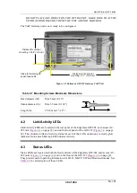
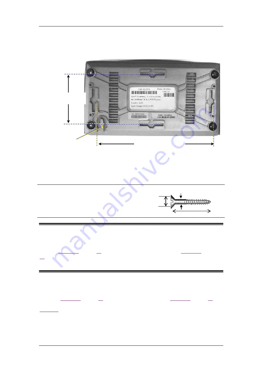
Clasp for fastening DC
power-feed cable
Figure 3-5 Bottom of GW-232 Gateway VoIP Unit
Table 3-1 Mounting Screws Maximum Dimensions
Head diameter (H):
Max 9 mm (0.35")
Shank diameter (S):
Max 3.5 mm (0.138")
Length (L):
25-30 mm (1"-1.2")
4.2
Link/Activity LEDs
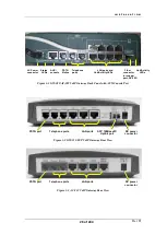
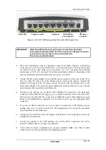
Link/Activity LEDs are located on the rear panel of the EdgeGate GW-282 and Access AC-
282 unit (
), and on the front panel of the GW-232 (
). They indicate Link and Activity status for each of the LAN connections. A steady glow
indicates Link, and a blinking LED indicates Activity.
4.3
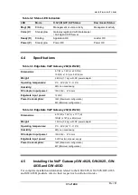
Status LEDs
Status LEDs are located on both the front and rear of the EdgeGate GW-282 and Access AC-
282 units (
) and on the front of the GW-232 (
).
They provide useful operating information for H.323, MGCP, SIP and Download modes. See
for a description of these LEDs.
Distance for vertical hanging
= 2.68” ( 6.8 cm)
Distance for horizontal
hanging = 6.1” ( 15.5 cm)
Distance for horizontal
hanging = 6.1” ( 15.5 cm)
Distance for horizontal
hanging = 6.1” ( 15.5 cm)
Distance for horizontal
hanging = 6.1” ( 15.5 cm)
Distance for vertical hanging
= 2.68” ( 6.8 cm)
Distance for horizontal
mounting = 6.1” ( 15.5 cm)
Distance for vertical
mounting = 2.68” ( 6.8 cm)
Summary of Contents for AC - 232 - TX
Page 4: ......
Page 24: ......
Page 44: ......
Page 50: ......
Page 68: ......
Page 79: ...C L I C O M M A N D M O D E S Rev H 79 of 244 Figure 9 4 Network Mode show and set Commands ...
Page 81: ...C L I C O M M A N D M O D E S Rev H 81 of 244 Figure 9 8 SIP Mode show and set Commands ...
Page 98: ......
Page 108: ......
Page 156: ......
Page 158: ......
Page 170: ......
Page 184: ......
Page 202: ......
Page 228: ......
Page 234: ......
Page 242: ......

