I N I T I A L C O N F I G U R A T I O N A N D B A C K G R O U N D I N F O R M A T I O N
Rev H
42 of 244
6
Initial Setup
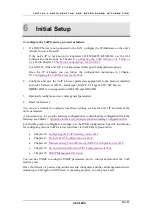
To configure the VoIP Gateway, proceed as follows:
1.
If a DHCP Server is not connected to the LAN, configure the IP Addresses on the unit’s
interface to use a Fixed IP.
If the unit’s IP is not known for EdgeGate 282/282S/482S/483S/483D, use the CLI
configuration instructions in Chapter 8,
Configuring the VoIP Gateway via Telnet or
, and in Chapter 18,
Network Configuration via Telnet/CLI
.
For GW-232, if the unit’s IP is not known use the Keypad Configurations options.
Once the IP is known you can follow the configuration instructions in 1Chapter
10,
Configuring the VoIP Gateway via the Web
2.
Configure and save the VoIP protocol parameters appropriate to the protocol installed
and to the Call server (H.323 - Gatekeeper; MGCP - Call agent; SIP - SIP Server).
NOTE:
H323 is not supported on GW-483S and GW-483D.
3.
Optionally configure and save other general parameters.
4.
Reset the Gateway.
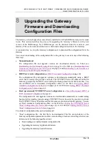
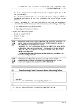
You can use a terminal to configure local basic settings, such as the unit’s IP and most of the
unit’s parameters.
A convenient way to set up the Gateway configuration is to download the configuration file to the
Gateway, see Chapter 7,
Upgrading the Gateway Firmware and Downloading Configuration Files
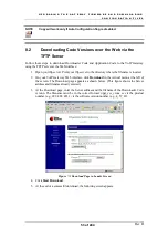
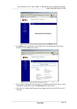
For flexible graphic configuration settings, use the WEB configuration. Specific instructions
for configuring various VoIP Gateway functions via the WEB are presented in:
•
Chapter 10:
Configuring the VoIP Gateway via the Web
•
Chapter 13:
Protocol H.323 Configuration via Web
•
Chapter 14:
Media Gateway Control Protocol (MGCP) Configuration via Web
•
Chapter 15:
Session Initiation Protocol (SIP) Configuration via Web
•
Chapter 16:
You can use SNMP to configure SNMP parameters, and to control and monitor the VoIP
Gateway unit.
Once the Gateway is powered up, addressed, and configured; and the call management device
(Gatekeeper, Call agent or SIP Server) is operating properly, you can place a call.
Summary of Contents for AC - 232 - TX
Page 4: ......
Page 24: ......
Page 44: ......
Page 50: ......
Page 68: ......
Page 79: ...C L I C O M M A N D M O D E S Rev H 79 of 244 Figure 9 4 Network Mode show and set Commands ...
Page 81: ...C L I C O M M A N D M O D E S Rev H 81 of 244 Figure 9 8 SIP Mode show and set Commands ...
Page 98: ......
Page 108: ......
Page 156: ......
Page 158: ......
Page 170: ......
Page 184: ......
Page 202: ......
Page 228: ......
Page 234: ......
Page 242: ......

