C O N F I G U R I N G T H E V O I P G A T E W A Y V I A T H E W E B
Rev H
91 of 244
11.4.2 VLAN Tagging on the VoIP Gateway
VLAN tagging is required to identify traffic from more than one VLAN on the same port. A
“tag” is simply the VLAN identification number (VLAN ID), as specified in the 802.1Q
standard. The tag is included in the packets forwarded across the LAN. You can allow the
VoIP Gateway to connect to non 802.1Q-compliant devices by adding/removing the tag from
packets according to tag definitions in the VLAN configuration table.
11.4.3 VLAN Configuration Procedure on the VoIP Gateway
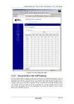
Use the TAB key or click to move around the table in the VLAN configuration page. The
VoIP Gateway is factory set with VLAN ID – 1 assigned by default to all the ports of the unit.
Each port must have a default ID. All packets received on the VoIP Gateway ports without a
VLAN tag will inherit the default VLAN ID of the receiving port as their VLAN ID.
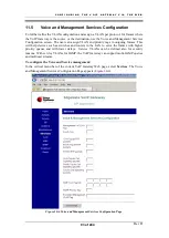
You can use the VLAN configuration page to define new VLANs.
To define a new VLAN, proceed as follows:
1. In the
VLAN
column, enter the new VLAN ID.
NOTE
For EdgeGate 282/282S/482S/483S/483D when IGMP is enabled, the Gateway
uses VLAN IDs in the range 1792-1842 internally. Therefore, VLAN IDs in this
range should not be used by the user.
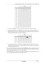
2. In the Ports table, in the row corresponding to the new VLAN ID:
In the column under the number of each port that is permitted to be a member of the new
VLAN (see figure below):
•
Enter
T
if packets of the VLAN are to be transmitted from the port
with
a VLAN
tag in the packet (Tagged).
•
Enter
U
if packets of the VLAN are to be transmitted from the port
without
a
VLAN tag in the packet (Untagged).
Note: The 232 product supports four LAN ports and up to eight VLANs.
Summary of Contents for AC - 232 - TX
Page 4: ......
Page 24: ......
Page 44: ......
Page 50: ......
Page 68: ......
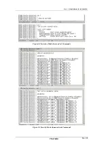
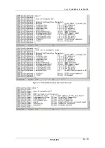
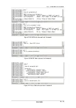
Page 79: ...C L I C O M M A N D M O D E S Rev H 79 of 244 Figure 9 4 Network Mode show and set Commands ...
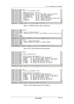
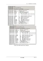
Page 81: ...C L I C O M M A N D M O D E S Rev H 81 of 244 Figure 9 8 SIP Mode show and set Commands ...
Page 98: ......
Page 108: ......
Page 156: ......
Page 158: ......
Page 170: ......
Page 184: ......
Page 202: ......
Page 228: ......
Page 234: ......
Page 242: ......

