GW-482S INSTALL ATION GUID E
20
MN100143 Rev B
Appendix A
Patch Panel Kit Installation
Required Equipment
•
Edge Gate Patch Panel Installation kit
•
Type-110 insertion tool
•
Recommended cables:
For 10/100BaseT X LAN ports connections, use shielded twisted pair 100 Ohm CAT
5, also called STP CAT 5 with a solid wire.
For phone connections, use standard telephone with solid wires
Installation Procedure
To begin installation, proceed as follows:
1.
Open the kit box.
2.
The kit is shipped with the following accessories:
•
AS100918 patch card
•
8 x HR000416 RJ45 to RJ45 cables
•
4 x HR000415 RJ11 to RJ11 cables
•
3 plastic tie strips
•
PK000100 pack with screws and washers
•
Patch Panel Installation Instructions.
3.
Open the Edge Gate cabinet door.
4.
Disconnect the AC power connector (plug).
5.
Disconnect battery.
6.
Insert the patch card into the unit
7.
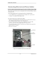
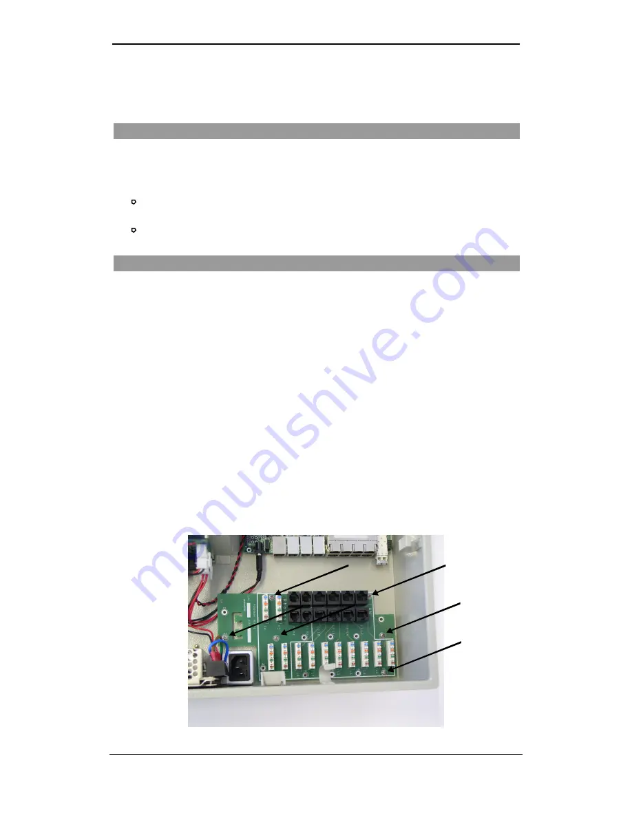
Mate the holes on the Patch Panel with the screw standoffs as seen in picture.
8.
Use the supplied screws and washers to assemble the panel to the cabinet. Refer to
picture for screw locations.
Figure 23: Inserting the Patch Panel into the Cabinet
Arrows indicate
screw positions.


