GW-482S INSTALL ATION GUID E
23
MN100143 Rev B
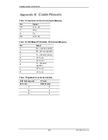
Appendix B
Cable Pinouts
Table 5: Telephone Interface Pin-to-Signal Mapping
Pin
Signal
1, 2
not in use
3
Ring
4
Tip
5, 6
not in use
Table 6: 10/100BaseT/TX Interface Pin-to-Signal Mapping
Pin
Signal
1
Rx + (receive positive)
2
Rx - (receive negative)
3
Tx + (transmit positive)
4
not in use
5
not in use
6
Tx – (transmit
negative)
7
not in use
8
not in use
Table 7: EdgeGate Console Serial Cable
VoIP Gatew ay side
PC side
RJ-45 Pin
DB-9 Female
3 2
6 3
5 5


