31
Installing the Equipment
2.5.4.1
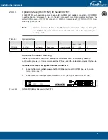
SCSI Interface (T1/E1) for the 3200-TE and 3200-TE+1
A 3200-TE and 3200-TE+1 with SCSI patch panels enables the connection to T1/E1 lines. The
termination impedance is set at 120 ohms. It is possible to connect an external balun in order to convert
to 75 ohms.
Note
All ports may not be active. T1/E1 ports are activated by software license; the number of
active ports depends on the licenses purchased.
Patch panels use straight connections. In other words, they do not cross the RX and TX
signals. Connections between patch panels and 3200 series 1+1 systems requires
straight cables. (The supplied SCSI cables are straight cables.) Cables that are used to
connect the network to the 1+1 patch panel must make the cross connection.
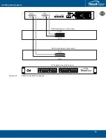
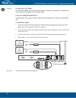
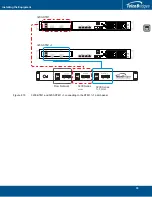
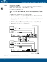
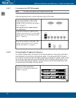
To connect both the 3200-TE and 3200-TE+1 (SCSI) to the PSTN:
1.
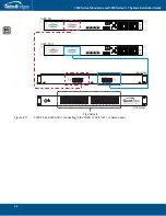
Connect each T1/E1 line from the network section of the 1+1 patch panel to the remote equipment.
See
2.
Connect SCSI ports 0-15 from the Gateway section at the rear of the 1+1 patch panel to the SCSI
ports 0-15 of the 3200-TE.
3.
Connect SCSI ports 16-31 from the Gateway section at the rear of the 1+1 patch panel to the SCSI
ports 16-31 of the 3200-TE.
4.
Connect SCSI ports 0-15 from the Gateway 1+1 section at the rear of the 1+1 patch panel to the
SCSI ports 0-15 of the 3200-TE+1.
5.
Connect SCSI ports 16-31 from the Gateway 1+1 section at the rear of the 1+1 patch panel to the
SCSI ports 16-31 of the 3200-TE+1.
Note:
To connect 32 more lines to the 3200-TE and the 3200-TE+1, install another 1+1 patch
panel and connect the additional 32 lines to ports 32-63 on each unit.

