TMG7800 Series System Installation Guide
16
3.
Repeat steps 1 and 2 for a second 7800 N+1 patch panel.
2.2.3.5
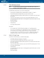
7800 1+1 Patch Panel
Mounting the 7800 1+1 Patch Panel(s):
1.
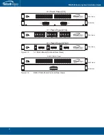
Using four metal screws, attach one angle bracket to the front, left-hand side of the 7800 1+1 patch
panel, when viewed from the front. Do the same for the angle bracket on the right-hand side.
2.
Start mounting this equipment beneath the last 7800-TMS, keeping in mind the space required on
the equipment rack as described in
Section
2.2.2 “Vertical Placement of the Equipment” on
page
14.
3.
If required, repeat steps 1 and 2 for a second 7800 1+1 patch panel.
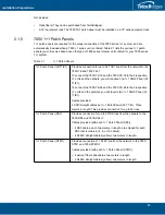
2.2.3.6
7800 RJ48C Patch Panel
Mounting the 7800 RJ48C Patch Panel(s):
1.
Using four metal screws, attach one angle bracket to the front, left-hand side of the 7800 RJ48C
patch panel, when viewed from the front. Do the same for the angle bracket on the right-hand side.
2.
Start mounting this equipment beneath the last 7800-TMS, keeping in mind the space required on
the equipment rack as described in Section
2.2.2 “Vertical Placement of the Equipment” on
page
14.
3.
If required, repeat steps 1 and 2 for a second 7800 RJ48C patch panel.

