TMG7800 Series System Installation Guide
34
4.3.3.1
Standalone Configuration
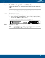
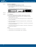
To connect the TMG7800-STM1 (Optical Interface) to the PSTN:
1.
Connect a fiber optic cable between the Port 0 (Main) port and OC3/STM1 line, as shown in
figure
4.7 on page
34.
2.
Connect a fiber optic cable between the Port 1 (APS) port and OC3/STM1 line.
Figure
4.7
Optical Interface to the PSTN
4.3.3.2
1+1 Configuration
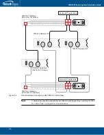
To connect both the 78007800-STM1 and 7800-STM +1 (Optical Interface) to the PSTN:
1.
Connect each OC3/STM1 line of the network section of the 1+1 patch panel to the remote
equipment. See figure
4.8 on page
35.
2.
Connect a fiber optic cable between STM1 of the Gateway section of the 1+1 patch panel and the
main port of the 7800-STM1.
3.
Connect a fiber optic cable between APS of the Gateway section of the 1+1 patch panel and the
APS port of the 7800-STM1.
4.
Connect a fiber optic cable between STM1 of the Gateway 1+1 section of the 1+1 patch panel and
the main port of the 7800-STM1 +1.
5.
Connect a fiber optic cable between APS of the Gateway 1+1 section of the 1+1 patch panel and
the APS port of the 7800-STM1 +1.
Optional
1.
Connect bits port 0 and 1 from the 7800-STM1 to the 1+1 patch panel
2.
Connect bits port 0 and 1 from the 7800-STM1+1 to the 1+1 patch panel
MGMT0
ETH
VOIP
0
1
0
1
TMS
0
1

