45
Installing the 7800-TMS
Section
5
Installing the 7800-TMS
This section covers the following procedures:
•
Section
5.1 “Connecting to the Control Network” on page
45.
•
Section
5.2 “Grounding the Equipment Chassis” on page
46.
•
Section
5.3 “Powering Up” on page
47.
5.1
Connecting to the Control Network
The Control network enables the communication between the 7800-CTRL, the 7800 Series Telecom
Unit(s), and the 7800-TMS.
Prerequisites
To connect the 7800-TMS, you will need:
•
Two CAT5 Ethernet cables with RJ45 male-male terminations.
Connections
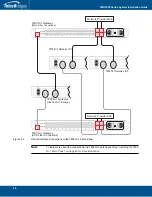
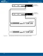
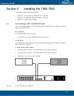
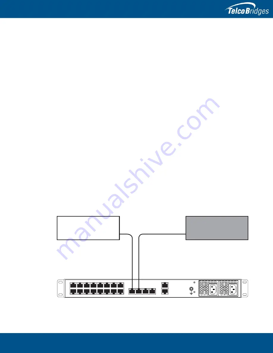
The 7800-TMS is connected to the 7800 series control network using two CAT5 Ethernet cables, as
shown in figure
5.1 on page
45.
To connect to the control network:
1.
Connect the ETH0 connector on the 7800-TMS to Control network switch one.
2.
Connect the ETH1 connector on the 7800-TMS to Control network switch two.
3.
Repeat step 1 and 2 for a second 7800-TMS.
Figure
5.1
Connecting to the Control Network
BITS0
BITS1
0
2
4
6
8
10
12
14
1
3
5
7
9
11
13
15
0
2
4
6
8
10
12
14
1010
ETH0
ETH1
Gigabit
Ethernet
Switch
Gigabit
Ethernet
Switch

