GB
GB
30
31
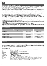
IMPORTANT INSTALLATION ADVICE
- The automation system must be installed to good workmanship standards by qualified staff meeting the legal
prerequisites, in accordance with machinery directive 2006/42/EC.
- Check the condition of any wiring already installed in the system.
- Analyse the risks of the automation system and adopt any appropriate safety and warning measures.
- Install cont rols such as the key -swi tch in such a way that the user is not in a hazard zone.
- After installation, try out the automation safety, signalling and release devices several times.
- Apply the CE lab l or nameplate containing the hazard information and ID information to the automation. .
- Consign the instructions for use, safety information and EC declaration of conformity to the final user.
- Ensure that the user has understood how to operate the automation correctly in automatic, manual and emergency
modes.
- Inform the user in writing (for example, in the operating instructions):
* of any residual risks for which no protection is provided, and foreseeable misuse .
* That the power supply must be disconnected in the event of cleaning in the area of the automation, or minor maintenance
work (e.g. repainting).
* That the automation must be inspected frequently for visible damage, informing the installer immediately if any damage is
found.
* That children must not be allowed to play in the immediate vicinity of the automation.
- That a maintenance schedule must be drawn up for the plant (at least every six months for the safety devices), recording
work done in a specific log.
SPRING SELECTION
RAPPER4TL
SNAPPER4
SN PSR
SN SRS
SN SRS + PSR
MSNYELLOW
MSNYELLOW
Bar type
Bar length
4 m
3 m
MSNGREEN
MSNGREEN
MSNGREEN
MSNGREEN
MSNGREEN
MSNGREEN MSNRED
/
MSNRED
MSNGREEN
CHARACTERISTICS
The SNAP4 is an electromechanical barrier suitable for use on the accesses to car parks, factories, public buildings, hospitals,
apartment buildings, etc.
It consists of a cabinet containing the gear motor and control unit. The drive system is irreversible with a manual release
facility.
Optional accessories
SNAPPER4
Circular section rigid bar, total length L4250 mm.
PAF
Fixed supporting foot.
PSR
Movable sporting foot.
SRS
Plastic skirt L2000 mm.
SNR
Articulated joint.
FIX SNAP4
Fixing accessories.
ADEK
Reflective adhesive for SNAPPER4 L4000 mm.
STICKERS
12 reflective stickers.
LEDSNAPPER
LED lights for SNAPPER4
CB24
24V battery charger, for use with 24V control unit.
SPB24
Outdoor installation box with 2 12V 7Ah batteries.
SUN POWER
Solar panel power supply kit suitable for installation on all 24 Vdc automation systems.
H230T
Heater to ensure gear motor operation even at low temperatures.
Power supply 230V power absorption 10W complete with thermostat.
PRELIMINARY CHECKS AND INSTALLATION ON THE GROUND
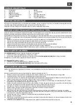
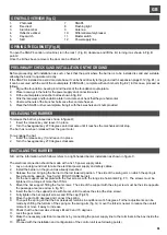
GENERAL OVERVIEW (fig. C)
1.
Photocells
2.
Fixed rest
3.
Aluminium bar
4.
Reflective sticker
5.
Key-switch
6.
Skirt
Before proceeding with installation as such, check that the point where the barrier is to be installed is solid and suitable,
allowing the barrier to operate correctly.
If the SNAP4 is installed on a solid concrete base, it can be fixed directly to the ground with 4 expansion plugs D.12 (fig. E1), or
it can be secured with the aid of the counterplate (FIXSNAP4), complete with anchor bolts (fig. E2); in this case, proceed as
follows:
1.
Dig out the foundation, bearing in mind the size of the foundation counterplate.
2.
Place raceways in the hole for the power supply and connection wires
3.
Fit the counterplate and anchor bolt as shown in fig. E2.
4.
Sink the raceways and foundation plate in concrete and check that they are horizontal.
5.
Unscrew the nuts of the 4 anchor bolts once the concrete has set..
6.
Place the SNAP4 on the counterplate, fixing it with the 4 washers and 4 nuts provided.
OPENING THE CABINET (Fig. B)
To open the SNAP4 control unit cabinet, turn the lock 1 (Fig. B) clockwise and lift the lid, turning it as shown in Fig. B
point 2.
Once the lid has been removed, the door can be lifted off.
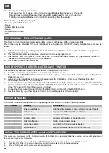
INSTALLING THE BARRIER
N.B.: all the information which follows refers to a right-handed barrier installation as shown in figure C.
The electrical connection should be made with a 3x1.5 power supply cable.
1.
Lay an underground duct to take the electrical power supply and safety cables.
2.
Install the barrier on the ground as already described.
3.
Release the rod, bringing the barrier to the rod lowered position. The side of the swing arm on which the spring is
fixed should be upward. See fig. G2 (RIGHT-HAND barrier).
4.
Fix the bar support anchor plate with the four screws, with the long side horizontal (Fig. F1). The screws must be
tightened to a torque of more than 70 Nm.
5.
Mount the bar support, fitting the four screws. The side of the support with the stop screw must be the side opposite
the passage area (see arrow in fig. F2).
6.
Insert the bar in the support (side with brace) until it reaches the stop (the stop screw).
7.
Fully tighten the bar support screws and fit the cap (Fig.F3).
8.
Move the bar to 90 degrees and connect the spring.
9.
Then pull the spring so that the bar (released) remains in equilibrium at 45 degrees. Further adjustments can be
made by shifting the fulcrum of the spring on the swing arm (fig. G): move the fulcrum nearer to reduce the overall
moment or move it away to increase.
10. Check that the bar remains virtually still at 20 and 70 degrees.
11.
Lock the gear motor.
12. Make the necessary electrical connections by connecting the power supply line to the terminals in the box inside the
cabinet.
13. Proceed with the installation and configuration of the control unit (see following points).
RELEASING THE BARRIER
To release the barrier, proceed as shown in figure D:
1.
Insert the release key and leave it in place.
2.
Turn the hexagonal key 270 degrees anti-clockwise until it reaches the mechanical limit stop.
The bar has now been released from the gear motor.
To re-engage the bar:
1.
Insert the release key (1) and leave it in place.
2.
Turn the hexagonal key 270 degrees clockwise.
7.
SNAP4
8.
Flashing light
9.
Antenna
10.
Differential safety breaker
11.
Master switch
12.
Power supply line
Summary of Contents for RAPPER4TL
Page 4: ...I F E GB D NL 270 Fig D min 200 mm 310 240 m in 400 227 160 min 350 Fig E1 Fig E2 4...
Page 5: ...I F E GB D NL Fig F Fig G 4 5...
Page 54: ...NOTE...
Page 55: ......


